Table of Contents
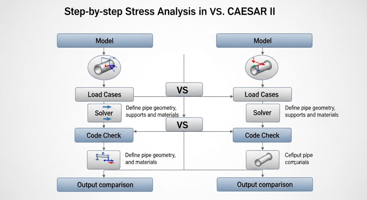
AutoPIPE vs CAESAR II Detailed Differences for Piping Stress Analysis
In my 20+ years of handling EPC projects—from methanol plants to ZLD systems—I’ve seen teams struggle not with choosing software, but understanding how each tool behaves under real stress conditions. During one methanol project, we validated the same steam header in both AutoPIPE and CAESAR II. The result? A 12–15% variation in sustained stress due to differences in default SIF handling and load combinations.
That’s where most engineers go wrong. They treat both tools as interchangeable, but in reality, they operate with very different philosophies—especially in load case generation, solver logic, and friction modeling.
- Clear comparison of AutoPIPE vs CAESAR II in real EPC conditions
- Deep insights into load case preparation and solver differences
- Practical understanding of friction, supports, and global parameters
- Field-tested recommendations for plant engineers and stress analysts
Interactive Engineering Quiz
Test your understanding of AutoPIPE vs CAESAR II with real stress analysis logic used in EPC projects.
Complete Course on
Piping Engineering
Check Now
Key Features
- 125+ Hours Content
- 500+ Recorded Lectures
- 20+ Years Exp.
- Lifetime Access
Coverage
- Codes & Standards
- Layouts & Design
- Material Eng.
- Stress Analysis
How load cases differ in practice
Load case formulation differences: CAESAR II uses explicit load case equations aligned with ASME B31.3 combinations, while AutoPIPE automatically builds essential sustained, expansion, and occasional cases with internal logic. The difference directly impacts stress compliance reporting and conservatism.
In CAESAR II, I define load cases manually:
EXP = (T1 – T2)
OCC = W + P + WIND
Each combination requires careful classification. If you misclassify EXP as SUS, the allowable stress limit reduces drastically:
Expansion allowable = f (1.25Sc + 0.25Sh)
AutoPIPE reduces this risk by auto-generating load cases. However, this also means:
- Less flexibility in custom combinations
- Higher dependence on default solver assumptions
- Limited control in special cases like slug flow or dynamic loads
Friction modeling solver behavior differences
Friction modeling differences: AutoPIPE uses nonlinear solver techniques to dynamically adjust friction states, while CAESAR II requires user-defined stiffness iterations and convergence tuning. This changes displacement predictions significantly.
For a support with friction coefficient μ = 0.3:
In CAESAR II:
- Friction activates based on displacement iteration cycles
- Requires convergence parameter tuning
- Can produce instability in large rack systems
In AutoPIPE:
- Friction state transitions automatically
- Solver manages stick-slip conditions internally
- Better convergence for large loops (observed in pipe racks)
Global parameter tuning engineering implications
Global parameter control differences: CAESAR II exposes solver tolerances, SIF libraries, and hanger design criteria to the user, while AutoPIPE hides many parameters under automated defaults. This creates a trade-off between control and speed.
Key CAESAR II parameters I typically adjust:
- Convergence tolerances
- Stress intensification factors (SIF)
- Rigid support stiffness values
- Hanger design settings
In contrast, AutoPIPE uses predefined libraries and intelligent defaults, reducing setup time but limiting engineering intervention.
| Parameter | AutoPIPE | CAESAR II |
|---|---|---|
| Load Case Generation | Automatic | Manual and flexible |
| Solver Type | Nonlinear automatic | Iterative user-controlled |
| Friction Handling | Automatic stick-slip | Requires tuning |
| Global Parameters | Limited access | Fully customizable |
| Learning Curve | Moderate | High |
| Best Use Case | Fast EPC modeling | Detailed stress analysis |
| Entity | Description | Standard Reference |
|---|---|---|
| SUS Stress | Sustained stress due to weight and pressure | ASME B31.1 |
| EXP Stress | Thermal expansion stress range | ASME B31.3 |
| OCC Load | Occasional load such as wind or seismic | ASME B31 codes |
| SIF | Stress intensification factor | ASME B31 Appendix D |
| Friction Coefficient | Resistance factor at supports | Engineering practice |
What engineers must validate before final stress reports
Site verification checklist: Before accepting stress analysis results from AutoPIPE or CAESAR II, engineers must validate load cases, support modeling, friction assumptions, and boundary conditions against actual site conditions and applicable ASME B31.3 and ASME B31.1 codes to avoid unsafe or overly conservative designs.
In my EPC experience, especially in methanol and ZLD projects, most stress analysis errors are not from software—they come from incorrect input assumptions. This checklist is what I personally use before freezing any model.
Load Case Verification
- Ensure sustained cases include weight and pressure correctly
- Verify expansion cases correctly represent operating temperature range
- Check occasional loads like wind, seismic, relief thrust
- Confirm correct stress category mapping (SUS, EXP, OCC)
Support and Boundary Condition Checks
- Validate support types match actual site supports (guide, line stop, anchor)
- Check support stiffness values for realistic behavior
- Ensure anchor points are not over-restricting the system
- Verify spring hanger loads and travel range
Friction and Interaction Validation
- Confirm friction coefficients based on actual material (steel on steel, PTFE, etc.)
- Check stick-slip behavior for large displacement systems
- Compare displacement results between restrained and friction cases
Geometry and Modeling Accuracy
- Verify pipe routing matches latest isometric drawings
- Ensure correct node spacing at bends, tees, reducers
- Confirm inclusion of all inline components (valves, strainers, equipment nozzles)
Code Compliance and Stress Limits
- Check allowable stress limits against applicable code
- Verify Stress Intensification Factors (SIF) used
- Review sustained, expansion, and occasional stress ratios
Displacement and Equipment Safety
- Validate nozzle loads against vendor allowable data
- Check displacement limits near rotating equipment
- Confirm thermal movement clearances at structures
Field Case Study: Methanol Plant Stress Behavior
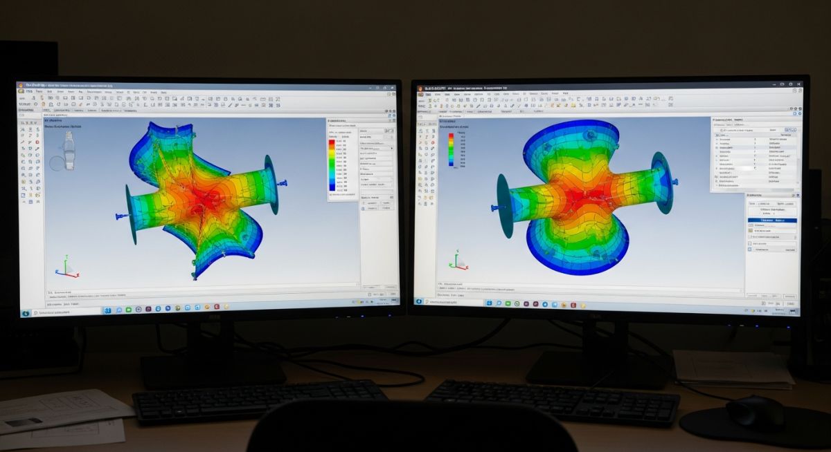
Field validation insight: AutoPIPE vs CAESAR II differences become visible when identical piping models produce varying stress ratios due to SIF libraries, solver convergence behavior, and load case classification based on ASME B31.3 Code Requirements. These variations must be interpreted, not blindly accepted.
In my experience, I model faster systems using AutoPIPE during EPC execution and validate all critical lines, especially near rotating equipment and high-temperature loops, using CAESAR II for tighter control.
Frequently Asked Engineering Questions
Which software fits EPC fast-track execution better
Why do AutoPIPE vs CAESAR II results differ
Does AutoPIPE reduce engineering accuracy
Which software handles friction conditions more reliably
When should CAESAR II be mandatory in projects
Can both AutoPIPE and CAESAR II be used together
Field Case Study: Real-World Application
Real project behavior difference: AutoPIPE and CAESAR II can produce different stress and displacement outputs for the same piping system due to solver assumptions, load case handling, and stress intensification factors based on ASME B31.3 requirements.
Based on multiple projects, I use AutoPIPE for fast EPC modeling and CAESAR II for critical validation where detailed code-level control is required.
Frequently Asked Engineering Questions
Which software is better for EPC projects
Why do stress results differ between tools
Is AutoPIPE less accurate than CAESAR II
Which tool handles friction better
When should CAESAR II be used
Can both tools be used together in projects

📚 Recommended Resources: AutoPIPE vs CAESAR II
Read these Guides

Related posts:
![Technician performing ultrasonic testing on a metal weld joint]()
Understanding the Meaning of Ultrasonic Testing of Welds
![3D structural model of a building undergoing seismic simulation with a response spectrum graph overlay.]()
What is Response Spectrum and Steps for Earthquake Response Spectrum Analysis
![3D architectural render of a modern skyscraper showing vector arrows representing structural loads.]()
Types of Loads on Structures: An In-Depth Guide
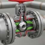
![Cutaway 3D render of an API 6D trunnion-mounted ball valve on an industrial pipeline.]()
Ultimate Engineering Guide to API 6D Valve Design and Testing
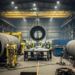
![Pressure vessel fabrication process in industrial workshop with welding and rolling operations]()
Pressure Vessel Fabrication Process Explained for Industrial Projects
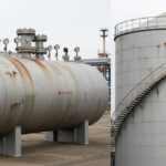
![Pressure vessel vs storage tank visual comparison industrial equipment]()
Pressure Vessels vs Storage Tanks Major Differences