Hydraulic Calculation Guidelines: Master Class for Process Piping in 2026
Core Knowledge Objectives
- Standardized Formulas: Master the application of Darcy-Weisbach and Colebrook-White in modern EPC workflows.
- Safety Limits: Identify critical erosional and sonic velocity thresholds to prevent pipe wall thinning.
- Efficiency: Balance capital expenditure (pipe size) against operating costs (pumping power) using 2026 economic indices.
What are Hydraulic Calculation Guidelines?
Hydraulic Calculation Guidelines are a set of engineering protocols used to determine the optimal pipe diameter, pressure drop, and fluid velocity within a piping system. These guidelines integrate fluid properties, pipe roughness, and fitting resistance to ensure the system meets process requirements while staying within safety limits defined by ASME B31.3 and API standards.
Expert Insight
“In over 20 years of process design, I have seen more field failures caused by incorrect hydraulic assumptions than by material defects. In 2026, the focus has shifted toward ‘Smart Hydraulics’—integrating real-time viscosity changes into your Hydraulic Calculation Guidelines to account for variable feedstocks.”
— Atul Singla, Founder of EPCLand
Table of Contents
Complete Course on
Piping Engineering
Check Now
Key Features
- 125+ Hours Content
- 500+ Recorded Lectures
- 20+ Years Exp.
- Lifetime Access
Coverage
- Codes & Standards
- Layouts & Design
- Material Eng.
- Stress Analysis
Which equation is considered the most accurate for determining the friction factor in Hydraulic Calculation Guidelines?
1. Purpose: Why We Use Hydraulic Calculation Guidelines
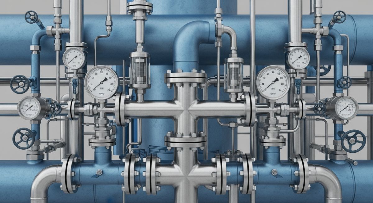
In the complex ecosystem of a process plant, the Hydraulic Calculation Guidelines serve as the mathematical blueprint for fluid transport. The primary objective is to define a piping system that delivers the required flow rate at the specified pressure and temperature while maintaining mechanical integrity. Without rigorous Hydraulic Calculation Guidelines, systems are prone to excessive vibration, premature pipe failure due to erosion, and inefficient energy consumption that can inflate operational costs by millions over a plant’s lifecycle.
Engineers must adhere to these guidelines to satisfy both safety and economic constraints. From a safety perspective, Hydraulic Calculation Guidelines ensure that the system does not exceed the ASME B31.3 pressure ratings and that pumps operate within their stable regions to avoid cavitation. Economically, these calculations allow for “Line Sizing Optimization,” where the capital expenditure of larger diameter pipes is weighed against the long-term electricity costs of the pumping units.
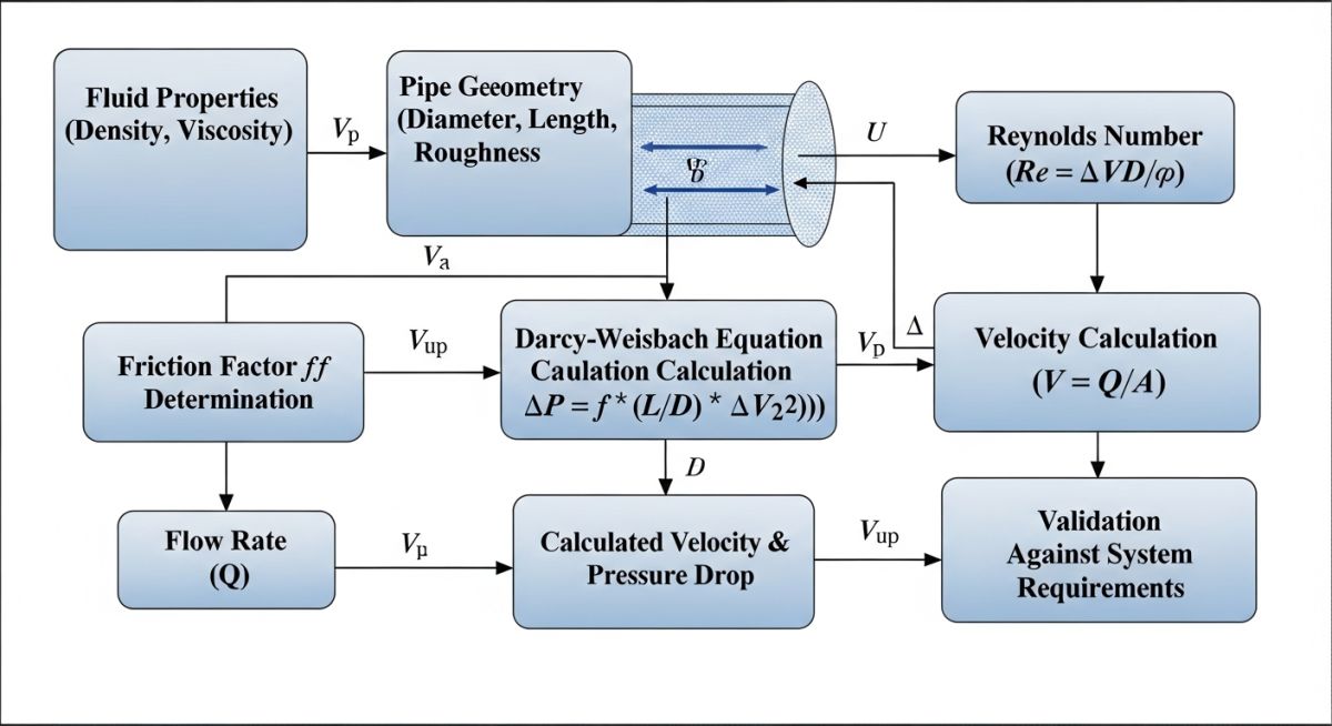
2. Step-by-Step Workflow for Hydraulic Calculation Guidelines
Executing Hydraulic Calculation Guidelines in a 2026 EPC environment requires a structured approach to ensure data consistency across disciplines. The process begins with the Process Data Sheet (PDS), which provides the fluid’s physical properties such as density, viscosity, and vapor pressure at operating conditions.
2.1 What are Data Required for Hydraulic Calculation?
Before opening any simulation software or spreadsheet, an engineer must compile a comprehensive “Input Data Set.” According to the latest Hydraulic Calculation Guidelines, the following parameters are non-negotiable:
- Fluid Properties: Mass flow rate, molecular weight (for gases), dynamic viscosity, and specific gravity.
- Piping Geometry: Proposed pipe routing, including total length, elevation changes (static head), and a count of all fittings (elbows, tees, valves).
- Equipment Constraints: Maximum allowable pressure drop across heat exchangers, filters, and control valves.
- Environmental Conditions: Ambient temperature ranges which may affect the viscosity of heavy oils or the density of gases.
Technical Insight: Input Data Integrity
The accuracy of your Hydraulic Calculation Guidelines is only as good as your physical property method. For hydrocarbon mixtures, always verify if the Peng-Robinson or NRTL equation of state is more appropriate for your specific pressure-temperature regime before proceeding with line sizing.
3. Hydraulic Calculation & Formulas
The core of all Hydraulic Calculation Guidelines lies in the relationship between friction and velocity. For 2026 standards, we rely heavily on the Darcy-Weisbach equation because of its universal applicability to any fluid, unlike the Hazen-Williams method which is limited to water at specific temperatures.
To maintain compliance with ASME B31.3 Process Piping Standards, the calculation of the Darcy friction factor (f) must be performed iteratively using the Colebrook-White equation for turbulent flow (Reynolds Number > 4000). For laminar flow (Reynolds Number < 2000), the simpler Hagen-Poiseuille relationship (f = 64/Re) is applied within the guidelines.
3. Core Formulas and Hydraulic Calculation Guidelines Standards
In 2026, the complexity of fluid transport systems demands a transition from “rule of thumb” estimations to precise mathematical modeling. The Hydraulic Calculation Guidelines prioritize the Darcy-Weisbach equation for calculating head loss due to friction, as it remains the most robust method across varying Reynolds numbers and pipe roughness values.
3.3 Limitation of Line Size: Velocity Thresholds
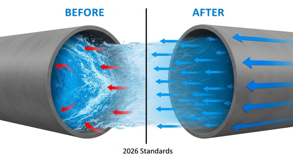
Modern Hydraulic Calculation Guidelines impose strict limits on fluid velocity to prevent mechanical degradation. Excessive velocity leads to noise, vibration, and erosion-corrosion, while insufficient velocity in slurry lines causes solids to settle, leading to blockages.
3.3.1 Erosional Velocity Formula
Per API RP 14E guidelines:
Ve = C / (ρ)0.5
Where C is the empirical constant (typically 100-125 for continuous service) and ρ is the fluid density. Following Hydraulic Calculation Guidelines ensures the actual velocity (V) stays below Ve.
3.3.2 Sonic Velocity (Choked Flow)
For gas and vapor systems:
Vs = (k * R * T / MW)0.5
In 2026 relief header designs, Hydraulic Calculation Guidelines recommend keeping the Mach number (V/Vs) below 0.7 for continuous flow to avoid acoustic induced vibration (AIV).
3.5 Pressure Drop Data and Industry Benchmarks
To maintain compliance with API Standards for Process Equipment, engineers must account for “Fixed” pressure drops across instruments and equipment before calculating the “Variable” friction loss in the piping itself.
| Service Type | Recommended Velocity (m/s) | Allowable ΔP (bar/100m) | 2026 Constraint |
|---|---|---|---|
| Pump Suction (Liquid) | 0.6 – 1.2 | 0.05 – 0.10 | NPSH Limit |
| Pump Discharge (Liquid) | 1.5 – 2.5 | 0.20 – 0.50 | OPEX Opt. |
| High Pressure Steam | 30.0 – 50.0 | 0.10 – 0.30 | Noise Limit |
| Slurry Lines | V > Vcritical | 0.50 – 1.00 | Erosion Risk |
3.4 Equivalent Length of Piping Components
Valves and fittings contribute significantly to the total pressure drop. The Hydraulic Calculation Guidelines utilize the “L/D” ratio method or the “K-factor” method for precise modeling. For example, a standard 90-degree elbow typically has an equivalent length (Le) equal to 30 times its diameter (30D), whereas a fully open gate valve adds only 8D.
2026 Interactive: Basic Pressure Drop Estimator
Quickly estimate liquid pressure drop per 100m using standard Hydraulic Calculation Guidelines logic (Darcy-Weisbach approximation).
Case Study: Choosing Between Hydraulic Calculation Guidelines for Plant Retrofits
The Challenge: Brownfield Expansion Cavitation
A brownfield refinery expansion in early 2026 required a 25% increase in throughput for a Vacuum Gas Oil (VGO) feed line. The existing 8-inch suction line was suspected to be insufficient for the new flow rate. Initial simplified models suggested the line was “adequate,” but field vibration reports indicated intermittent cavitation at the pump suction.
The Solution: Applying Rigorous Hydraulic Calculation Guidelines
The engineering team applied the 2026 Hydraulic Calculation Guidelines, moving beyond simple velocity checks. They utilized the Colebrook-White equation to account for the increased absolute roughness of the 15-year-old carbon steel pipe (estimated at 0.5mm due to corrosion).
Outcome Metrics
- ✔ Line Size Upgrade: 8″ to 10″ increased NPSHa by 1.4m.
- ✔ Vibration Reduction: 70% decrease in peak-to-peak suction pulse.
- ✔ Energy Savings: Estimated $12,000/year reduction in pumping power due to lower friction head.
Key Learning
This case confirms that following Hydraulic Calculation Guidelines for aged piping requires adjusting the absolute roughness (ε) values. Using “new pipe” parameters in a brownfield environment is a leading cause of undersized hydraulic circuits and equipment failure.
EPCLand YouTube Channel
2,500+ Videos • Daily Updates
Expert Insights: Lessons from 20 years in the field
Refining Hydraulic Calculation Guidelines for high-stakes EPC projects requires more than just plugging numbers into a simulator. After two decades of overseeing piping hydraulics for global refineries, these are the critical technical nuances that distinguish a “functional” design from an “optimal” one:
-
01
Margin for Fouling: Never assume “clean” pipe roughness in your Hydraulic Calculation Guidelines for cooling water or crude oil service. In 2026, we mandate a 15-20% pressure drop contingency to account for internal scaling and bio-fouling over the first 5 years of operation.
-
02
Control Valve Authority: Ensure the control valve takes at least 25-30% of the total system friction drop at maximum flow. If the valve is too large (low pressure drop), it loses control sensitivity, leading to flow hunting and instability.
-
03
Two-Phase Flow Regimes: For mixed-phase hydraulics, the Hydraulic Calculation Guidelines must include a Baker Plot or Mandhane Map analysis. Transitioning from “slug flow” to “annular flow” can cause a 10x increase in local vibration forces that simple Darcy equations cannot predict.
-
04
Static Head Trap: In 2026, we emphasize checking “no-flow” static pressure. If your Hydraulic Calculation Guidelines only focus on dynamic losses, you might miss that a high-elevation header could exceed the pipe’s flange rating during a pump trip scenario.
References & Standards
The following official standards form the regulatory basis for the Hydraulic Calculation Guidelines presented in this guide:
Frequently Asked Questions: Hydraulic Calculation Guidelines
What is the most critical factor in Hydraulic Calculation Guidelines for pump suction?
How do 2026 standards handle absolute pipe roughness?
Can I use Hazen-Williams for hydrocarbon lines?
What is the “Human Hook” risk in neglecting erosional velocity?
Why does Atul Singla emphasize “Control Valve Authority”?
Is software-based hydraulic calculation always better than manual?

Related posts:
![Industrial worker welding a large structural steel I-beam in a fabrication facility.]()
What is Structural Steel Fabrication and How Does It Work?
![A heavy-duty stainless steel turnbuckle tensioning a structural cable.]()
What is a Turnbuckle and How to Install It?
![Stack of newly manufactured galvanized steel pipes in an industrial warehouse]()
Understanding the Galvanized Pipe Meaning in Modern Piping Systems
![Industrial Alloy 625 piping components in a manufacturing plant]()
What is Alloy 625? Properties, Grades, and Applications of Alloy 625
![Close-up of a fractured steel shaft showing metal fatigue beach marks and failure zones.]()
What is Metal Fatigue and How Do Engineers Prevent It?
![Industrial machinery fitted with smart sensors displaying real-time condition-based maintenance data on a digital overlay.]()
What is Condition-Based Maintenance and How Does It Work?