Types, Applications, and Selection of Choke Valves for Oil and Gas Operations
Imagine a wellhead kicking with 10,000 PSI of reservoir pressure, carrying a volatile mix of crude, corrosive CO2, and abrasive formation sand. Without the precision of high-spec Choke Valves for Oil and Gas, this raw energy would vaporize downstream piping in minutes. You aren’t just choosing a valve; you are designing the primary barrier that dictates the life cycle and safety of your production manifold.
This guide moves beyond basic definitions to provide an engineering-grade breakdown of trim selection, API 6A compliance, and the thermodynamic realities of the Joule-Thomson effect in modern 2026 oilfield operations.
Key Engineering Takeaways
- Pressure Management: Understand how Choke Valves for Oil and Gas handle extreme pressure drops through staged trim designs.
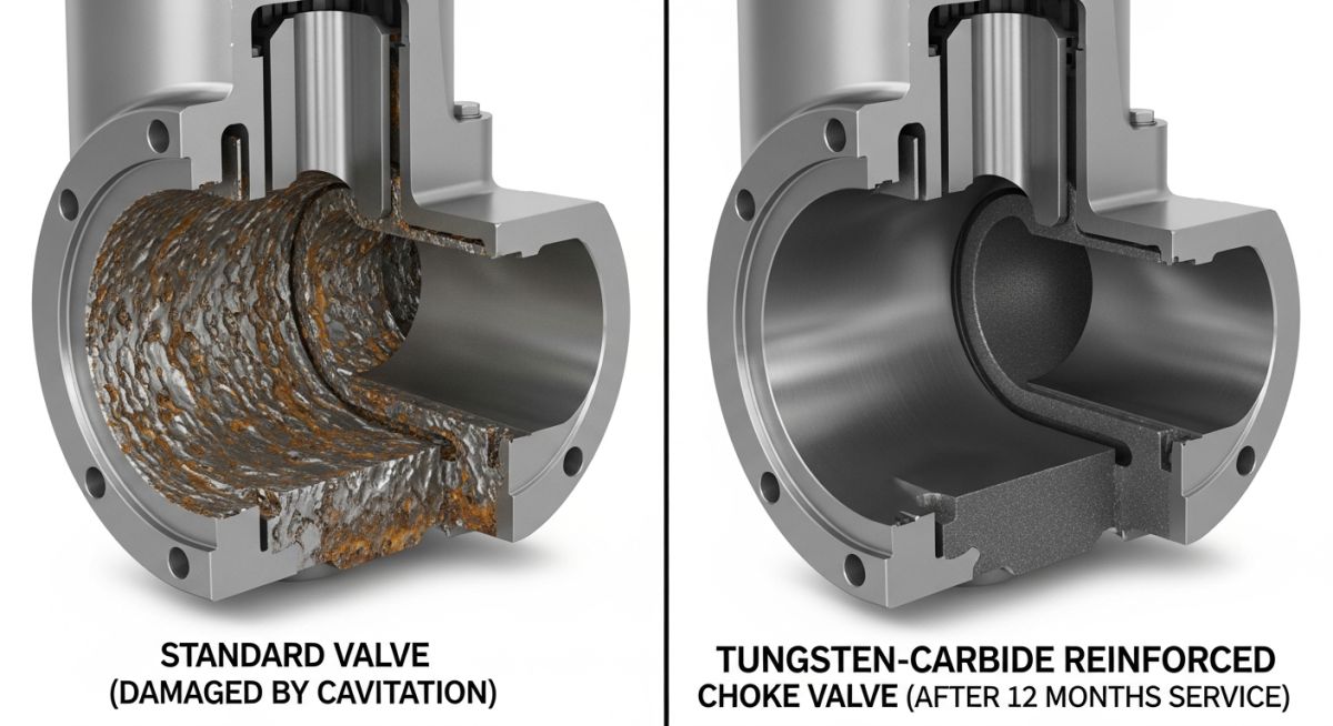
- Material Integrity: Why tungsten carbide and specialized alloys are non-negotiable for erosion resistance in high-velocity flow.
- Operational Logic: The critical distinction between fixed beans for steady production and adjustable chokes for well cleanup.
What are Choke Valves for Oil and Gas?
Choke Valves for Oil and Gas are specialized flow control devices used primarily at wellheads and manifolds to regulate fluid production and manage downstream pressure. They function by creating a deliberate pressure drop, utilizing adjustable or fixed orifices to control flow rates and protect downstream equipment from high-pressure reservoir surges.
“In my 20 years across offshore assets, I’ve seen more manifold failures due to poor choke sizing than almost any other component. In 2026, as we push into deeper, high-pressure reservoirs, your understanding of trim exit velocity is what stands between steady production and a catastrophic washout.”
– Atul Singla, Founder
Complete Course on
Piping Engineering
Check Now
Key Features
- 125+ Hours Content
- 500+ Recorded Lectures
- 20+ Years Exp.
- Lifetime Access
Coverage
- Codes & Standards
- Layouts & Design
- Material Eng.
- Stress Analysis
Engineering Check: Choke Valves for Oil and Gas
Test your technical knowledge on API 6A flow control.
Question 1 of 5
Which API specification primarily governs the design and material requirements for Choke Valves for Oil and Gas?
Critical Applications of Choke Valves for Oil and Gas
In the upstream sector, Choke Valves for Oil and Gas serve as the primary interface between high-pressure reservoirs and atmospheric or low-pressure processing facilities. Their application is dictated by the need to manage severe pressure drops while maintaining a stable flow rate. On wellheads, these valves are utilized during the initial flow-back period to filter out completion fluids and solids, protecting the downstream separators from damage. Furthermore, in gas lift operations, Choke Valves for Oil and Gas precisely meter the injection of high-pressure gas into the wellbore to optimize lift efficiency.
Beyond the wellhead, these valves are critical in production manifolds where multiple wells of varying pressures converge into a single flowline. By adjusting the choke settings, engineers can prevent high-pressure wells from “back-pressuring” lower-pressure wells, ensuring total field production is maximized. In 2026, the integration of smart actuators with Choke Valves for Oil and Gas allows for real-time reservoir management, adapting to fluctuating water cuts and gas-oil ratios (GOR) without manual intervention. For detailed design requirements, engineers frequently reference the API Standards for Production Equipment.
Major Types of Choke Valves for Oil and Gas
The classification of Choke Valves for Oil and Gas is fundamentally split between their adjustability and their internal trim geometry. Selecting the wrong type can lead to premature failure via erosion or cavitation, particularly in “dirty” service where sand or proppant is present.
Regulating Choke Valves for Oil and Gas
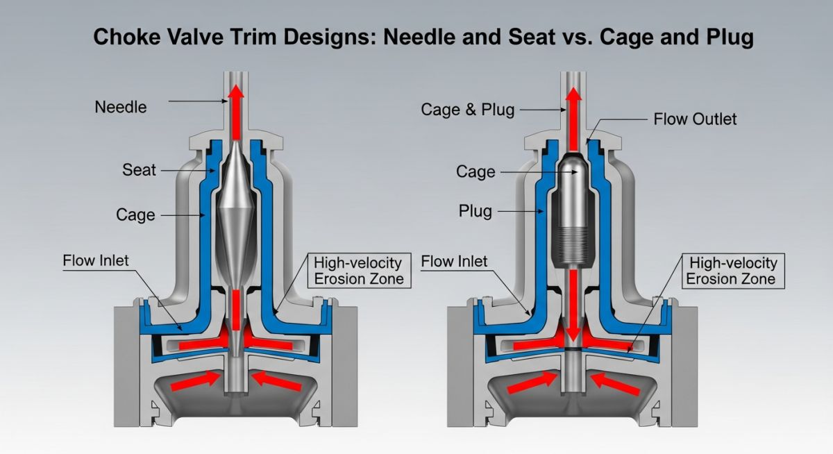
Regulating (or adjustable) Choke Valves for Oil and Gas allow for continuous variation of the orifice size while the valve is under pressure. This is achieved through several mechanical designs, most commonly the needle-and-seat or the cage-and-plug. The needle-and-seat design is ideal for fine control in low-flow gas applications but is highly susceptible to erosion in sandy fluid streams. Conversely, the cage-and-plug design utilizes a perforated cylinder (the cage) and a moving plug to reveal or hide flow ports. This design dissipates energy within the center of the cage, significantly reducing the impact of high-velocity fluid on the valve body itself.
Non-regulating Choke Valves for Oil and Gas
Non-regulating (or fixed) Choke Valves for Oil and Gas utilize a “choke bean”—a replaceable insert with a fixed-diameter hole. These are the workhorses of steady-state production. Because there are no moving internal parts in the flow stream, fixed chokes are inherently more robust and less prone to mechanical failure. In 2026 operations, fixed chokes are preferred for mature fields where reservoir pressure has stabilized, and the flow rate remains consistent over long durations. Replacing a bean requires the valve to be isolated and depressurized, making them less flexible than their adjustable counterparts but far more cost-effective for long-term service.
Design Standards of Choke Valves for Oil and Gas
The engineering integrity of Choke Valves for Oil and Gas is strictly governed by the API Spec 6A (Specification for Wellhead and Tree Equipment). This standard defines the Material Class (AA through HH) based on the concentration of CO2 and H2S, ensuring the valve body and internals can withstand sour service without sulfide stress cracking. Furthermore, the ASME B16.34 standard provides the framework for pressure-temperature ratings, while NACE MR0175 compliance is mandatory for any Choke Valves for Oil and Gas operating in environments where hydrogen-induced cracking is a risk.
Standard Symbols for Choke Valves for Oil and Gas
In Process and Instrumentation Diagrams (P&IDs), Choke Valves for Oil and Gas are represented by a standard valve butterfly symbol with an additional “Z” or a diagonal line to indicate a throttle or choke function. An adjustable choke typically includes an arrow pointing through the valve, signifying its variable orifice capability. Accurate symbology is vital for 2026 digital twin integration, where automated control systems must distinguish between a standard isolation gate valve and a modulating Choke Valve for Oil and Gas.
Essential Functions of Choke Valves for Oil and Gas
The primary function is the management of the Joule-Thomson Effect. As high-pressure gas expands across the orifice of Choke Valves for Oil and Gas, the temperature drops significantly. Engineers must calculate this drop to prevent hydrate formation, which can plug the line. Secondary functions include:
- Back-pressure Maintenance: Preventing reservoir sand influx by maintaining a minimum bottom-hole pressure.
- Flow Measurement: Using the pressure differential across a known bean size to estimate production rates.
- Equipment Protection: Shielding downstream separators and heaters from upstream pressure surges.
Working Principle of Choke Valves for Oil and Gas
The working principle relies on the conversion of potential energy (pressure) into kinetic energy (velocity). As fluid passes through the restricted orifice of Choke Valves for Oil and Gas, its velocity increases to a maximum at the “vena contracta.” This high-velocity jet is where the majority of pressure energy is dissipated. In 2026, advanced “Multi-stage” trims are used to break this pressure drop into several smaller steps, preventing cavitation bubbles from collapsing against the valve wall and causing “pitting” damage.
Engineering Selection of Choke Valves for Oil and Gas
| Feature | Needle & Seat | Cage & Plug |
|---|---|---|
| Primary Fluid | Clean Gas / Light Oil | Heavy Oil / Sandy Crudes |
| Erosion Resistance | Low (Edge Wear) | High (Center-stream Dissipation) |
| Control Precision | Excellent (Fine Increments) | Moderate to High |
| Common Rating | API 5,000 – 10,000 PSI | API 10,000 – 20,000 PSI |
Strategic Advantages of Choke Valves for Oil and Gas
Utilizing high-performance Choke Valves for Oil and Gas ensures operational longevity. By selecting trims made from Tungsten Carbide or Stellite, operators reduce the Frequency of Intervention (FoI). Furthermore, modern adjustable chokes allow for “automated well-ramping,” which prevents the sudden pressure shocks to the reservoir that often lead to premature water breakthrough. For further study on valve reliability, consult the ISO 10423 Standards for Drilling and Production.
Choke Valve Sizing Estimator (Liquid Service)
Estimate the required Flow Coefficient (Cv) for Choke Valves for Oil and Gas based on your production parameters.
Note: This calculation uses the standard liquid flow formula. For gas service or multi-phase flow in Choke Valves for Oil and Gas, specialized API 6A sizing software is required.
EPCLand YouTube Channel
2,500+ Videos • Daily Updates
Case Study: Mitigating Severe Erosion in Choke Valves for Oil and Gas
The Challenge
An operator in the Permian Basin experienced weekly failures of needle-style Choke Valves for Oil and Gas due to high proppant (sand) returns following a hydraulic fracturing campaign.
The Solution
Replacement of standard needle trims with Tungsten Carbide Cage and Plug designs. The cage was engineered with sacrificial thickness to absorb particle impact energy.
The Result
Mean Time Between Failure (MTBF) increased from 7 days to 14 months. Production uptime improved by 12%, saving approximately $450,000 in annual maintenance and deferred oil.
Engineering Analysis
The failure was attributed to "exit velocity" exceeding 150 ft/s. By utilizing multi-stage cage trims in the Choke Valves for Oil and Gas, the pressure drop was segmented, keeping local velocities below the threshold where sand becomes highly erosive. This transition is a standard recommendation in 2026 for unconventional well completions.
Operators should verify trim materials against the API 6A surface hardness requirements to ensure longevity in such abrasive environments.
Don't miss this video related to Choke Valves
Summary: Master Piping Engineering with our complete 125+ hour Certification Course: ......
Expert Insights: Lessons from 20 years in the field
Velocity is the Silent Killer
In high-pressure Choke Valves for Oil and Gas, the trim doesn't usually fail from pressure—it fails from fluid velocity. Always calculate the trim exit velocity; if it exceeds 100 ft/s in sandy service, you are looking at a washout within months, regardless of material hardness.
Hydrate Management in 2026
The Joule-Thomson cooling effect can drop temperatures below 32°F even in desert environments. Ensure your Choke Valves for Oil and Gas are positioned upstream of the line heater or have dedicated methanol injection points to prevent catastrophic hydrate plugging.
Automation Lag
When transitioning to automated Choke Valves for Oil and Gas, ensure your actuator duty cycle matches the reservoir pulsing. A standard hydraulic stepping actuator is far superior to cheap electric alternatives for high-frequency adjustments.
References & Standards
Frequently Asked Questions: Choke Valves for Oil and Gas
What is the primary purpose of Choke Valves for Oil and Gas? ▼
How do I choose between a fixed and an adjustable choke? ▼
What materials are best for erosive choke service? ▼
Can the Joule-Thomson effect cause Choke Valves for Oil and Gas to freeze? ▼
Why does my choke valve vibrate excessively at low openings? ▼
What is the significance of the 1/64th inch bean size? ▼
📚 Recommended Resources: Choke Valves
Read these Guides

Related posts:
![Industrial worker welding a large structural steel I-beam in a fabrication facility.]()
What is Structural Steel Fabrication and How Does It Work?
![A heavy-duty stainless steel turnbuckle tensioning a structural cable.]()
What is a Turnbuckle and How to Install It?
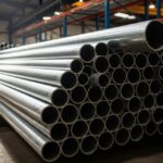
![Stack of newly manufactured galvanized steel pipes in an industrial warehouse]()
Understanding the Galvanized Pipe Meaning in Modern Piping Systems
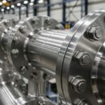
![Industrial Alloy 625 piping components in a manufacturing plant]()
What is Alloy 625? Properties, Grades, and Applications of Alloy 625
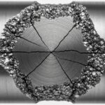
![Close-up of a fractured steel shaft showing metal fatigue beach marks and failure zones.]()
What is Metal Fatigue and How Do Engineers Prevent It?
![Industrial machinery fitted with smart sensors displaying real-time condition-based maintenance data on a digital overlay.]()
What is Condition-Based Maintenance and How Does It Work?