Mastering 3-Phase Separator Design Basics for Oil and Gas
In my 20 years of commissioning upstream oil and gas facilities, I have seen many projects stumble because of a failure to grasp the fundamentals of phase separation. A 3-phase separator is not just a simple tank; it is the heart of the primary processing facility. When you are dealing with high-pressure well streams containing gas, crude oil, and produced water, getting the vessel dimensions and internals right is the difference between a smooth-running plant and a continuous operational nightmare.
Throughout my career, I have reviewed hundreds of manufacturer datasheets and witnessed firsthand how minor errors in calculating retention times or droplet settling velocities lead to massive liquid carryover or gas carryunder. In this guide, I will share the practical engineering steps, equations, and field-tested insights that define successful vessel design.
Key Takeaways
- Understand the physical laws governing gravity separation and droplet settling.
- Learn how to calculate vessel diameter and length using standard industry formulas.
- Identify the critical internal components that prevent liquid carryover and gas carryunder.
- Discover how to avoid common field pitfalls like foaming, paraffin buildup, and emulsion layers.
Complete Course on
Piping Engineering
Check Now
Key Features
- 125+ Hours Content
- 500+ Recorded Lectures
- 20+ Years Exp.
- Lifetime Access
Coverage
- Codes & Standards
- Layouts & Design
- Material Eng.
- Stress Analysis
How to Apply 3-Phase Separator Design Basics
To design an efficient 3-phase separator, we must balance three distinct separation processes: gas-liquid separation, oil-water separation, and gas-liquid mist elimination. Each of these processes is governed by specific physical laws and design standards, primarily API Spec 12J and ASME Section VIII Division 1.
1. Gas Capacity and the Souders-Brown Equation
The maximum allowable gas velocity inside the vessel is determined by the Souders-Brown equation. This equation balances the drag force exerted by the rising gas stream against the gravitational force pulling the liquid droplets downward:
Where:
- V_g = Maximum allowable gas velocity (ft/s)
- rho_l = Liquid density (lb/ft³)
- rho_g = Gas density (lb/ft³)
- K = Empirical design factor (ft/s), which depends on the type of mist extractor used. For standard mesh pads, K typically ranges from 0.30 to 0.35. For high-capacity vane packs, K can reach 0.40 to 0.50.
2. Liquid-Liquid Separation and Stokes’ Law
The separation of oil and water phases relies on gravity settling. Because water is denser than oil, water droplets suspended in the oil phase settle downward, while oil droplets entrained in the water phase rise. For laminar flow conditions, this terminal settling velocity is calculated using Stokes’ Law:
Where:
- V_t = Terminal settling velocity of the droplet (ft/s)
- g = Acceleration due to gravity (32.2 ft/s²)
- d = Droplet diameter (ft)
- rho_w = Density of the water phase (lb/ft³)
- rho_o = Density of the oil phase (lb/ft³)
- mu_o = Dynamic viscosity of the continuous oil phase (lb/ft·s)
In practical design, we target the removal of water droplets down to 100 to 150 microns from the oil phase, and oil droplets down to 150 to 200 microns from the water phase. If the operating temperature is low or the oil viscosity is high, the settling velocity decreases significantly, requiring a larger vessel diameter or longer retention times.
In my field experience, ignoring the presence of a tight emulsion layer is the quickest way to cause separator failure. If the well stream contains high concentrations of surfactants or fine solids, a stable emulsion “rag layer” will form at the oil-water interface. This layer does not follow Stokes’ Law and can quickly grow to block the weir, leading to severe water carryover into the oil outlet. Always design for adequate chemical injection points and interface level control.
3. Vessel Internals and Their Functions
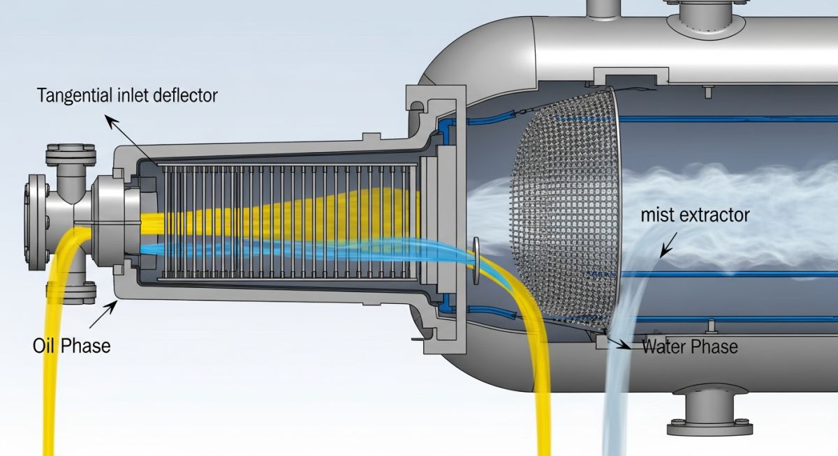
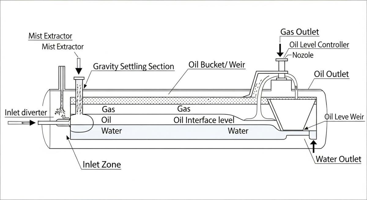
A successful design relies heavily on the selection and placement of vessel internals:
- Inlet Deflector: Diverts the incoming fluid, causing an initial momentum change that separates the bulk gas from the liquid phase. Common types include deflector plates, half-pipe inlets, and cyclonic devices.
- Coalescing Plates: A series of closely spaced parallel plates or structured packing that promotes the coalescence of small water droplets into larger ones, accelerating the gravity settling process.
- Weir Plate: A vertical baffle that maintains a constant oil level in the settling section while allowing the lighter oil phase to spill over into the oil bucket for discharge.
- Mist Extractor: Located near the gas outlet to capture fine liquid mist (typically down to 10 microns) from the gas stream. Mesh pads are common, but vane packs are preferred if solid fouling or paraffin is expected.
The table below outlines typical liquid retention times based on API gravity. These values are standard industry starting points for sizing calculations under normal operating conditions.
| Oil API Gravity (degrees) | Typical Operating Temp (°F) | Oil Retention Time (minutes) | Water Retention Time (minutes) |
|---|---|---|---|
| Above 35° API (Light) | 100 – 150 | 3 – 5 | 3 – 5 |
| 25° to 35° API (Medium) | 80 – 120 | 5 – 10 | 5 – 10 |
| 15° to 25° API (Heavy) | 60 – 100 | 10 – 20 | 10 – 20 |
| Below 15° API (Extra Heavy) | Under 60 | 20 – 30+ | 20 – 30+ |
| Design Parameter | Acronym / Symbol | Standard Unit | Applicable Code / Reference |
|---|---|---|---|
| Gas Capacity Factor | K-Value | ft/s (m/s) | API Spec 12J |
| Vessel Shell Thickness | t_shell | inches (mm) | ASME Sec VIII Div 1 |
| Inlet Momentum Limit | rho * v² | lb/(ft·s²) | API RP 14E |
| Corrosion Allowance | CA | inches (mm) | Project Specification / ASME |
Essential Steps for 3-Phase Separator Design Basics
Before finalizing any 3-phase separator design, I always run through a rigorous verification checklist. This ensures that the physical constraints of the site, the chemical properties of the fluids, and the mechanical limits of the vessel are fully aligned with ASME Section VIII guidelines.
Vessel Design Verification Checklist
-
Inlet Nozzle Momentum Check: Verify that the inlet momentum (rho * v²) does not exceed 1000 lb/(ft·s²) for standard deflectors, or 1500 lb/(ft·s²) for cyclonic inlets to prevent fluid shearing.
-
Sloshing and Motion Analysis: For offshore or floating installations (FPSOs), ensure that internal baffles are designed to mitigate liquid sloshing and maintain stable interface levels.
-
Weir Height Optimization: Confirm that the weir height is at least 6 inches above the maximum water level to prevent water from spilling over into the oil bucket during surge conditions.
-
Sand Jetting and Drain Systems: For heavy sand-producing wells, verify that sand jetting lines and bottom drains are included to prevent solids accumulation from reducing the active settling volume.
-
Mist Extractor Selection: Ensure the mist extractor is rated for the minimum and maximum design gas flow rates to avoid bypass or liquid re-entrainment.
Field Case Study: Real-World Application
During a commissioning project in the Permian Basin, a newly installed horizontal 3-phase separator experienced severe liquid carryover into the gas outlet line. The gas stream was carrying high volumes of crude oil mist, which fouled the downstream compressor valves and caused an unscheduled plant shutdown. The operator’s initial reaction was to blame the mist extractor, but my investigation revealed a deeper design flaw: the vessel was operating with an undersized liquid retention volume, causing the liquid level to rise too close to the gas velocity path, which sheared the liquid surface.
I recalculated the vessel’s liquid-gas interface dynamics and recommended retrofitting the inlet with a high-efficiency cyclonic inlet deflector to replace the basic flat plate. We also adjusted the weir height and reprogrammed the level control loop to maintain a lower, more stable oil-water interface. These modifications reduced the gas velocity at the liquid interface, allowing the mist extractor to function within its design limits. The plant resumed operations with zero liquid carryover, saving the operator over 150,000 per day in lost production and maintenance costs.
This case highlights why understanding the interaction between gas velocity and liquid levels is a core requirement of vessel design. You cannot treat these phases as isolated systems; they are dynamic and highly dependent on one another.
Frequently Asked Engineering Questions
What is the primary difference between a 2-phase and a 3-phase separator?
How does foaming affect the sizing of a 3-phase separator?
What is the typical droplet size target for water-in-oil separation?
Why is the weir height critical in horizontal 3-phase separators?
How do you select between a mesh pad and a vane pack mist extractor?
Which ASME code governs the design of these pressure vessels?

📚 Recommended Resources: 3-phase separator design basics

Related posts:
![Large industrial green ammonia storage tank with cryogenic piping and renewable energy infrastructure in the background.]()
Green Ammonia Storage Systems Design and Industrial Safety Protocols
![Industrial water supply system feeding a large-scale green hydrogen electrolyzer plant.]()
Water Requirement for Green Hydrogen Plants: Engineering Design and Optimization
![Industrial Air Separation Unit facility showing compression, purification, and cryogenic distillation columns for gas production.]()
Air Separation Unit Explained: Engineering Principles and Industrial Gas Production
![Cross-section diagram of a Solid Oxide Electrolyzer Cell stack for hydrogen production.]()
SOEC Electrolyzer Explained: High Temperature Electrolysis for Green Hydrogen Production
![Conceptual diagram of renewable energy assets and a hydrogen electrolyzer within the same EU bidding zone boundary.]()
Understanding RFNBO Geographic Correlation Rules for Green Hydrogen Projects
![Modern container ship utilizing green ammonia as marine fuel in a global port.]()
Green Ammonia as Marine Fuel: Engineering the Future of Shipping