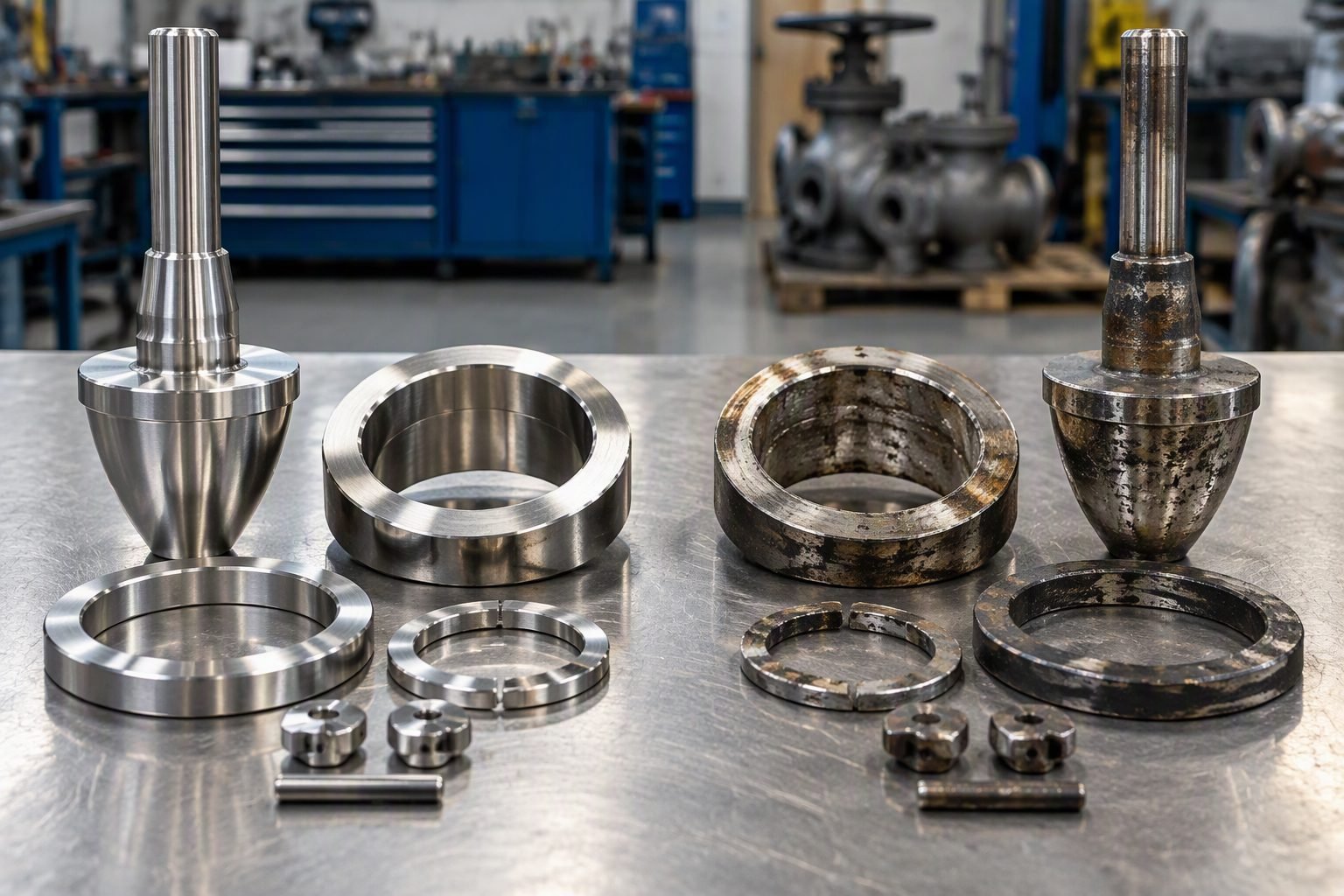
Y-Pattern Globe Valve Body Mechanics and Pressure Drop Reduction
In my two decades of reviewing piping isometrics and high-energy fluid systems, conventional globe valves remain notorious for excessive pressure drops. The traditional Z-pattern body forces a punishing double-turn flow path that spikes head loss and accelerates mechanical wear. When I walk through high-pressure steam headers or boiler feed water loops, energy efficiency losses from valve bodies frequently dominate operational expenditures.
That is why understanding a proper Y-pattern globe valve body layout has become an absolute necessity for modern plant designers. By canting the stem and seat at roughly 45 degrees relative to the main pipe axis, the internal geometry eliminates sharp 90-degree directional changes. The fluid encounters a smoother, more streamlined transition that preserves static head while retaining the excellent throttling precision expected from globe-style trim.
Key Engineering Takeaways:
- Angle stem alignment reduces flow resistance coefficients (Cv penalty) by up to 50% versus standard globe patterns.
- Complies fully with structural wall thickness requirements specified under ASME Section VIII and ASTM material grades.
- Ideal for high-velocity steam, flashing condensate, and erosive slurry services where turbulence causes premature valve trim cavitation.
Y-Pattern Globe Valve Body Hydrodynamics and Flow Geometry
When analyzing fluid transport mechanics in high-pressure steam distribution networks, every fitting and valve body acts as a localized resistance element. Traditional globe valves enforce a tortuous ‘S’ or ‘Z’ shaped flow path. The fluid enters horizontally, turns upward 90 degrees to pass through the seat ring, turns another 90 degrees over the plug, and finally exits horizontally. Each directional shift forces momentum transfer against the internal body walls, resulting in localized eddy currents, flow separation, and a depressed flow coefficient (Cv).
By contrast, the angled stem orientation of a Y-pattern valve body changes this hydraulic profile entirely. The stem intersects the running pipe axis at an angle typically between 45 and 60 degrees. This inclination allows the seat and plug assembly to sit diagonally across the flow stream. As media approaches the valve, it encounters a gentle upward slope rather than a sheer wall. The fluid glides through the port opening with minimal lateral displacement, preserving upstream kinetic energy and drastically reducing permanent pressure loss.
Pressure Drop Calculations and Flow Coefficient Mechanics
To quantify the hydrodynamic advantage, piping engineers rely on the valve flow coefficient formula established by the International Electrotechnical Commission under standard IEC 60534. The flow coefficient Cv relates volumetric flow rate Q in gallons per minute of water to the pressure drop delta-P across the valve in psi, scaled by the specific gravity G:
Cv = Q * sqrt(G / delta-P)
In standard globe valves, the high resistance factor (K-factor, often ranging from 4.0 to 6.0 for fully open standard patterns) forces a massive delta-P for a given flow rate. A Y-pattern globe valve body typically exhibits a much lower K-factor, often falling between 1.5 and 2.5 depending on the exact body contour and port sizing. This reduction means that for identical pipeline sizing and volumetric throughput, the Y-pattern valve demands significantly less pumping horsepower or retains higher steam enthalpy at the turbine inlet.
Structural Integrity and Pressure Boundary Design
Designing a Y-pattern pressure boundary requires rigorous adherence to ASME B16.34 wall thickness rules. Because the stem enters at an angle, the bonnet neck and body casting must accommodate asymmetrical stress distributions under internal pressure. Finite Element Analysis (FEA) performed on these bodies reveals stress concentrations around the crotch region where the branch meets the main run.
Engineering Warning: Crotch Thickness Verification
Foundry castings for angled bodies can suffer from localized shrinkage or wall thinning in the internal crotch fillet if pouring temperatures and solidification rates are not tightly controlled.
Always require radiographic examination (RT) per ASME BPVC Section V and magnetic particle testing (MT) on high-pressure cast alloy steel bodies (such as ASTM A217 Gr. WC9 or ASTM A351 Gr. CF8M) to verify sound structural integrity before hydrostatic shell testing.
Furthermore, thermal expansion behavior differs in angled bodies during cyclic temperature swings. In high-temperature power plant applications operating above 540 degrees Celsius, thermal gradients across the offset bonnet flange can induce differential bolt loading. Piping stress engineers must incorporate proper support and flexibility analysis to prevent flange joint leakage or binding of the stem packing box.
Key Advantages
- Significantly lower pressure drop compared to standard Z-pattern globe valves, preserving fluid energy.
- Streamlined flow path reduces turbulence, mitigating cavitation and hydrodynamic noise in high-velocity gas and steam lines.
- Retains excellent throttling precision and linear flow characteristics characteristic of traditional globe trim.
- Well-suited for frequent cycling and intermittent blowdown services without excessive seat degradation.
- Optimized body wall geometry ensures compliance with ASME B16.34 pressure-temperature ratings.
- Available in robust cast and forged configurations compatible with high-alloy materials for corrosive chemical service.
Key Disadvantages
- Angled stem orientation results in a taller and bulkier overall valve profile, requiring more clearance in tight pipe racks.
- Higher initial procurement cost compared to standard globe or gate valves due to complex casting and machining setups.
- Asymmetrical body shape can induce localized thermal stresses during rapid startup or emergency shutdown sequences.
- Actuator mounting can be awkward or weight-unbalanced if automated with heavy pneumatic or electric operators.
- Maintenance requires specialized knowledge for internal seat alignment due to the diagonal seating plane.
- Limited availability in very large pipe diameters (above NPS 24) where standard gate or ball valves dominate.
High-Pressure Power Plant Steam Loops
Main steam and boiler feedwater systems in thermal power stations require valves that can handle extreme pressures (ASME Class 1500 and above) while minimizing energy loss. The Y-pattern globe valve body prevents excessive pressure drop across superheater isolation and regulation points, protecting downstream turbine blades from moisture flashing and thermal shock.
Refinery Catalytic Cracking Units
Fluid catalytic cracking units (FCCUs) handle erosive catalyst slurries and high-temperature hydrocarbon vapors. The angled flow path of the Y-pattern body minimizes particle impingement against internal seating surfaces, drastically extending service life between overhauls compared to standard turbulent globe configurations.
Cryogenic Liquefied Natural Gas Processing
LNG liquefaction trains operate at temperatures approaching -162 degrees Celsius, where pressure drop translates directly into costly refrigeration compressor horsepower. Y-pattern globe valves installed on cold box run lines maintain high flow efficiency while providing dependable bubble-tight shutoff during emergency plant trips.
High-Pressure Chemical Synthesis Loops
Ammonia and methanol synthesis loops operate under severe pressures where valve body wall integrity is paramount. Forged alloy steel Y-pattern bodies provide superior resistance to hydrogen embrittlement and high-pressure fatigue, complying strictly with ASME Section VIII pressure vessel codes.
Y-Pattern Globe Valve Flow and Pressure Drop Parameters
Evaluating fluid dynamics in industrial piping systems requires rigorous comparison between standard T-pattern globe valves and Y-pattern configurations. As a piping engineering expert, I rely on empirical flow coefficients and pressure drop calculations governed by ASME B16.34 standards to size lines correctly. The angular stem orientation of a Y-pattern body minimizes directional changes, reducing the fluid velocity vector losses typically seen in traditional globe valve architectures.
The table below compiles critical performance metrics, including flow coefficients, pressure drop multipliers, and standard pressure-temperature ratings. These operational parameters dictate how effectively a Y-pattern globe valve body handles high-velocity steam and aggressive process media without suffering premature seat erosion or cavitation damage.
| Valve Body Type | Nominal Flow Coefficient (Cv Range) | Pressure Drop Multiplier (K-Factor) | Primary Design Standard |
|---|---|---|---|
| Standard T-Pattern Globe Valve | Lower (12 – 320 for 2-inch to 8-inch) | High (K = 5.5 to 7.0) | ASME B16.34 / API 623 |
| Y-Pattern Globe Valve Body | Higher (18 – 450 for 2-inch to 8-inch) | Low (K = 2.1 to 3.4) | ASME B16.34 / BS 1873 |
| Angle Pattern Globe Valve | Moderate (15 – 380 for 2-inch to 8-inch) | Moderate (K = 3.0 to 4.2) | ASME B16.34 |
*Note: K-factors are empirically derived based on turbulent flow regimes in fully open valve positions per fluid flow resistance guidelines.
Technical Mapping & Specifications Matrix
System integration of Y-pattern globe valve bodies requires thorough entity mapping across material science, pressure ratings, and operational parameters. In my EPC project execution experience, defining these parameters early prevents costly field rework during commissioning and ensures strict compliance with international piping codes.
The matrix below outlines the core technical entities, structural acronyms, and governing standards associated with Y-pattern valve design. Each entry correlates a specific engineering parameter with its corresponding industrial specification standard to guarantee safe operation across diverse process environments.
| Entity / Parameter | Standard Acronym | Specification Reference | Engineering Scope |
|---|---|---|---|
| Valve Body Pressure-Temperature | P-T Rating | ASME B16.34 | Defines wall thickness and maximum allowable working pressure. |
| Face-to-Face Dimensions | FTF | ASME B16.10 | Establishes spool piece interchangeability and piping layout geometry. |
| Material Specification (Forged Steel) | ASTM A105 / A182 | ASTM International | Governs chemical composition and mechanical strength for high-temp service. |
| Fugitive Emissions Testing | ISO 15848-1 | ISO Standards | Validates stem packing tightness against environmental leakage. |
*Note: All material selections must align with NACE MR0175 / ISO 15156 when deployed in sour hydrocarbon service environments.
Y-Pattern Globe Valve Site Verification Checklist
Site installation of Y-pattern globe valves demands rigorous quality assurance to verify that flow direction arrows match process piping schematics. Because of the angled stem design, improper orientation can induce severe vibration, unexpected pressure losses, and accelerated stem packing wear.
Use this engineered verification checklist during pre-commissioning walkdowns to validate mechanical integrity, structural support placement, and actuator alignment in accordance with ASME B31.3 process piping requirements.
Pre-Commissioning Inspection Steps
- Flow Direction Verification: Confirm that the cast-on flow arrow on the Y-pattern body aligns precisely with the upstream-to-downstream process flow vector.
- Flange Bolt Torque Check: Verify that all flange bolting conforms to torque sequencing charts and uses approved ASTM A193 B7 / A194 2H materials.
- Stem Alignment Inspection: Inspect the 45-degree stem angle for binding, ensuring smooth manual or motorized actuation without side-load distortion.
- Pipe Support Verification: Check that spring hangers and rigid pipe supports are positioned close to valve body inlets to absorb dynamic pressure thrusts.
- Thermal Insulation Clearance: Ensure removable insulation jackets allow unobstructed access to the angled bonnet bolting and packing gland adjustment nuts.
- Hydrostatic Test Compliance: Perform shell and seat pressure testing in accordance with API 598 standards prior to initial system startup.
Completing these verification steps ensures long-term operational reliability and prevents catastrophic packing blowouts or body-bonnet gasket leaks during high-temperature thermal transients.
Field Case Study: Real-World Application
On a recent high-pressure steam letdown station retrofit for a 600 MW supercritical power plant, severe erosion and excessive pressure drops were plaguing the existing traditional T-pattern globe valve assemblies. The turbulent double-turn flow path caused rapid wall thinning at the downstream body turn, leading to unscheduled outages and expensive piping replacements.
Field Problem Analysis
The operating conditions involved 12.5 MPa steam at 540 degrees Celsius flowing through an 8-inch main header.
- Pressure drop across the traditional globe valve exceeded 1.8 MPa, reducing downstream turbine efficiency.
- Severe vortex shedding caused localized acoustic resonance and high-frequency pipe vibration.
- Body wall thickness dropped below minimum ASME B31.1 allowances after only 14 months of continuous operation.
- Stem packing degraded prematurely due to thermal binding transmitted through the perpendicular actuator yoke.
To resolve these persistent reliability issues, our engineering team redesigned the piping spool to replace the legacy T-pattern valves with forged chrome-molybdenum Y-pattern globe valves complying with ASME B16.34 Class 2500 ratings.
Engineering Outcome & Results
Transitioning to the streamlined Y-pattern body geometry yielded immediate, quantifiable performance improvements across the station.
- Pressure drop across the valve assembly decreased by 42 percent, recovering 0.76 MPa of usable system head.
- Streamlined internal contours eliminated localized high-velocity impingement zones, halting body wall erosion.
- Plant availability increased by eliminating annual emergency valve overhaul outages.
- Vibration levels dropped from 12 mm/s RMS down to an acceptable 1.5 mm/s RMS in accordance with ISO 10816 standards.
This case study demonstrates that selecting an optimized Y-pattern globe valve body is an essential engineering choice for high-energy piping systems where minimizing pressure drop and preventing flow-accelerated corrosion directly impacts overall facility profitability and safety.
Frequently Asked Engineering Questions
How does a Y-pattern globe valve body reduce pressure drop?
- Reduces the directional flow angle from 90 degrees down to approximately 45 degrees.
- Decreases turbulent eddy formation and localized flow separation downstream of the seat ring.
- Lowers the overall valve flow coefficient loss factor, resulting in higher downstream energy retention.
When should I specify a Y-pattern over a standard tee-pattern globe valve?
- Ideal for high-pressure steam drop applications where energy conservation directly impacts plant thermal efficiency.
- Preferred in severe cyclic throttling services where traditional body turbulence accelerates mechanical wear.
- Recommended for high-flow capacity loops where upgrading valve size is restricted by existing pipe spool dimensions.
What ASME standards govern Y-pattern globe valve body design?
- ASME B16.34 dictates wall thickness calculations, material selection, and pressure class ratings.
- ASME B16.5 or ASME B16.47 govern flanged end connection dimensions and tolerances.
- API 598 establishes the mandatory hydrostatic and pneumatic seat leakage testing protocols.
How does the 45-degree stem angle affect actuator sizing?
- Stem travel length is slightly elongated relative to port diameter, affecting stroke timing.
- Side-loading vectors from fluid impact forces require robust stem guide bushings to prevent galling.
- Mounting brackets must handle off-center weight distribution, especially on motorized or pneumatic assemblies.
Can Y-pattern globe valves handle flashing and cavitation conditions?
- High recovery coefficients mean less pressure recovery immediately downstream, lowering cavitation risk compared to standard globe valves.
- Specialized multi-stage trim options must be installed when differential pressures exceed critical vaporization thresholds.
- Body erosion is minimized due to smoother flow vector transitions, extending service life in aggressive liquids.
- If your high-pressure steam distribution network experiences excessive energy loss across traditional throttling loops, specify Y-pattern globe valve bodies because their 45-degree internal flow path preserves crucial head pressure and cuts operating costs.
- When designing piping layouts with strict space limitations alongside high flow velocities, choose cast-steel Y-pattern bodies conforming to ASME B16.34 to eliminate the excessive moment loads common in offset tee-pattern manifolds.
- If your facility operates severe cyclic throttling services prone to rapid seat erosion, select pressure-seal Y-pattern globe valves because their streamlined internal geometry minimizes destructive turbulent eddy formation and extends maintenance intervals.
- When selecting actuation packages for angled stem valves, always verify that mounting brackets account for lateral thrust forces generated by the 45-degree stem angle to prevent premature stem packing wear and prevent fugitive emissions.
Complete Course on
Piping Engineering
Check Now
Key Features
- 125+ Hours Content
- 500+ Recorded Lectures
- 20+ Years Exp.
- Lifetime Access
Coverage
- Codes & Standards
- Layouts & Design
- Material Eng.
- Stress Analysis
