Wind Turbine Foundation Loads: Mastering the Four Critical Forces
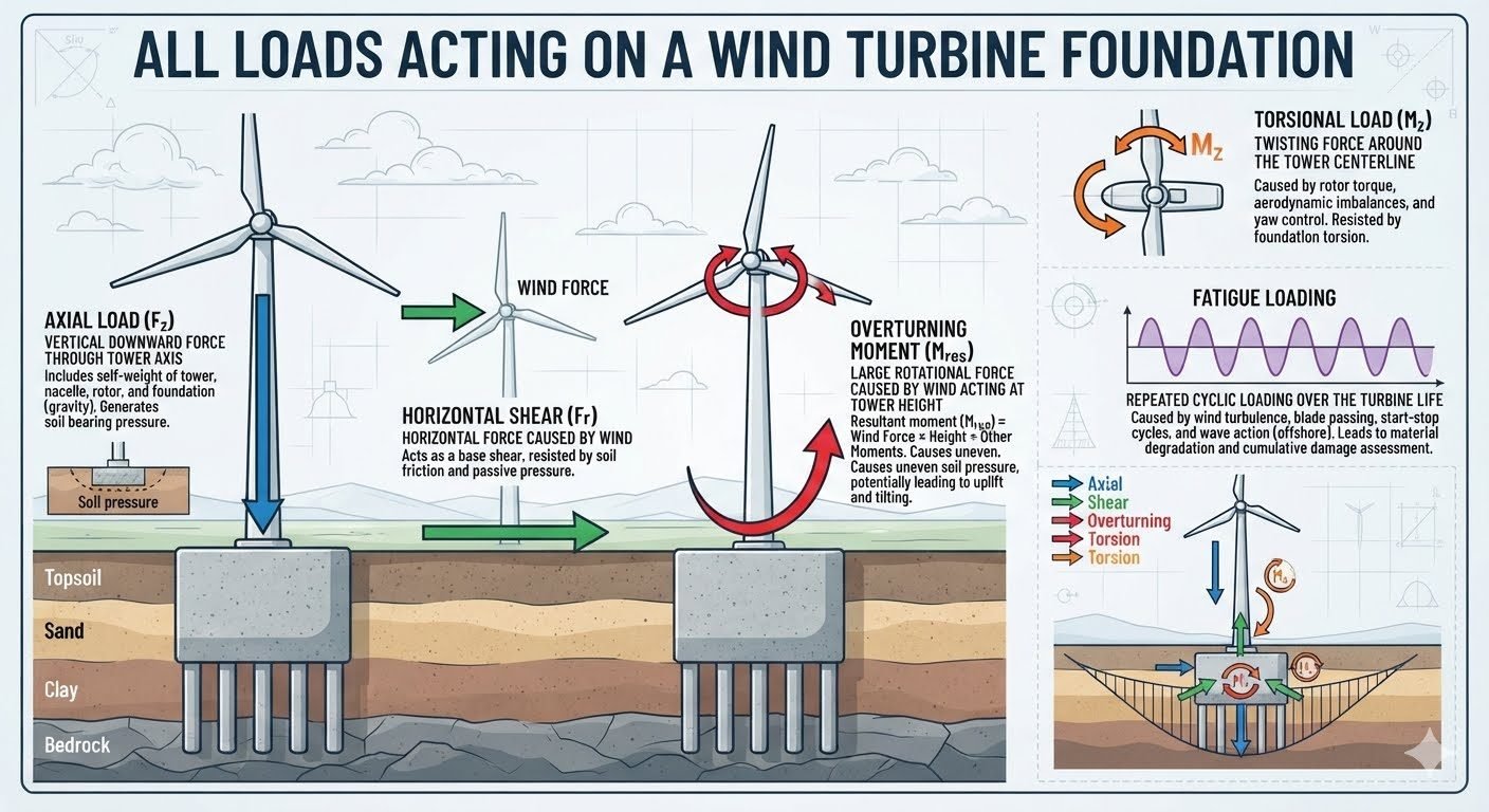
In my two decades of industrial structural design, I have observed that few civil structures experience the complex, multidirectional fatigue environments native to utility-scale wind energy installations. All loads acting on a wind turbine foundation reduce to four fundamental types that together dictate geotechnical stability, soil-structure interaction, and long-term dynamic resilience. Whether you are designing shallow gravity bases for onshore wind farms or massive piled jackets for deepwater offshore developments, accurately quantifying these forces is non-negotiable for preventing catastrophic tilting, sliding, or structural fatigue failure.
Engineers must look beyond static dead weight to capture the relentless amplification caused by turbulent wind gusts, rotor imbalances, and cyclic wave slamming. By synthesizing geotechnical soil parameters with rigorous structural mechanics governed by international standards, we establish safe operational envelopes that protect multi-million-dollar turbine assets over their twenty-to-thirty-year design lifecycles.
Key Engineering Takeaways:
- Deconstruct wind turbine structural demand into axial, shear, overturning, and torsional load components.
- Master the geotechnical mechanisms of soil bearing pressure, base shear friction, and passive resistance.
- Incorporate cyclic fatigue evaluations to account for wind turbulence, wave action, and operational start-stop frequencies.
Four Fundamental Wind Turbine Foundation Loads and Geotechnical Mechanics
1. Axial Load (Fz) Mechanics and Soil Bearing Pressure
Axial Load (Fz) is the vertical downward force transmitted through the tower axis to the foundation subgrade. This force combines the self-weight of the tower shell, heavy internal nacelle machinery, high-speed and low-speed rotating rotor assemblies, internal electrical transformers, and the substantial self-weight of the concrete and reinforcing steel foundation structure itself.
From a geotechnical perspective, the primary function of Fz is generating uniform and eccentric soil bearing pressure beneath shallow gravity base slabs or driving axial skin friction and end-bearing resistance in deep pile groups. When calculating ultimate bearing capacity according to ASTM D1583 guidelines, engineers must factor in effective stress distribution, consolidation settlement rates, and long-term creep in cohesive clay subgrades.
2. Horizontal Shear (Fr) and Sliding Resistance
Horizontal Shear (Fr) represents the massive lateral force generated by high-velocity wind streams sweeping across the expansive rotor swept area and exerting drag across the entire tubular or lattice tower profile. This shear force acts directly at the foundation-soil interface, creating a base sliding tendency that must be resisted entirely by base friction, soil cohesion, and passive earth pressure mobilized against the vertical sides of the embedded foundation block.
In soft soils where base friction is insufficient, civil engineers introduce shear keys, battered piles, or micropile anchors to increase lateral stiffness. The factor of safety against sliding is evaluated by comparing total resisting shear to applied lateral load, maintaining strict code compliance under ASCE 7 wind load combinations.
3. Overturning Moment (M_res) and Uplift Mitigation
The Overturning Moment (M_res) is arguably the most severe design driver in wind turbine foundation engineering. Because wind force acts at the hub height—often exceeding 100 to 150 meters above ground level—it creates an enormous rotational moment arm. This moment translates into extreme edge pressures, causing highly uneven soil pressure distributions across the foundation footprint.
If the overturning moment outpaces the stabilizing moment provided by the dead weight of the structure, edge lifting occurs. This can lead to a partial loss of contact area, sudden bearing capacity failure, progressive tilting, and ultimate structural collapse. Foundation footprints are therefore engineered with massive octagonal or circular diameters to maximize the restorative moment arm.
4. Torsional Load (Mz) and Foundation Torsional Stiffness
Torsional Load (Mz) is the twisting force acting around the vertical centerline of the tower. This moment is generated by aerodynamic rotor torque imbalances, sudden emergency braking actions of the drivetrain, and active yaw control mechanisms constantly orienting the heavy nacelle into shifting wind vectors.
While often secondary compared to overturning moments, torsional loads induce significant shear stresses in anchor bolt cages, ring beams, and concrete pedestals. The foundation must possess adequate torsional stiffness and rotational restraint to prevent micro-cracking at the grout-concrete interface and bolt fatigue failure over millions of operational cycles.
Critical Design Warning: Edge Pressure and Soil Liquefaction
Failure to accurately model dynamic overturning moments under extreme storm conditions can lead to excessive edge pressures that exceed allowable soil bearing capacity. In saturated sandy soils, cyclic shear and overturning stresses can trigger pore water pressure buildup, resulting in catastrophic liquefaction and foundation sinking. Always perform comprehensive cyclic triaxial soil testing before finalizing foundation geometry.
Cyclic Fatigue Loading and Cumulative Damage Assessment
Beyond ultimate design loads, wind turbines operate within harsh, continuous dynamic environments. Repeated cyclic loading over a twenty-five-year operational life—driven by atmospheric turbulence, blade passing frequency, start-stop cycles, and wave action in offshore installations—leads to cumulative material degradation.
Engineers apply Miner’s rule and S-N fatigue curves to evaluate cumulative damage ratios in reinforcing steel, prestressing tendons, and offshore grouted connections. This rigorous fatigue assessment ensures that micro-cracks do not propagate into structural failures prematurely, satisfying strict safety margins required by international offshore and onshore certification bodies.
Structural Advantages
- Gravity base mass naturally resists overturning moments through dead weight stabilization.
- Spread footings eliminate expensive offshore driving equipment in shallow onshore soil strata.
- Deep pile configurations effectively transfer axial loads through soft upper soils to competent bedrock.
- Massive concrete volumes provide high inherent damping against resonant vibrational frequencies.
- Standardized formwork allows rapid and repeatable civil construction sequences across large wind farm sites.
Structural Disadvantages
- Extremely high material consumption for mass concrete gravity slabs increases carbon footprint.
- Massive footprint requirements demand extensive land clearing and excavation civil works.
- Vulnerability to differential settlement in heterogeneous soil profiles causing tower misalignment.
- Complex reinforcement detailing required around anchor bolt cages to resist severe torsional moments.
- High sensitivity to long-term cyclic degradation and soil stiffness loss under continuous wave and wind loading.
Onshore Flat Terrain Gravity Foundations
Deployed extensively in plains and agricultural regions where soil bearing capacity is moderate near the surface. These massive octagonal gravity slabs rely on heavy dead weight to counteract extreme overturning moments generated by atmospheric wind shear while distributing high axial loads safely across compacted subgrades.
Offshore Monopile Foundation Structures
Utilized in shallow to transitional offshore waters where massive steel cylinders are driven deep into seabed strata. These structures must withstand combined wave slamming, current drag, and severe aerodynamic overturning moments while transferring tremendous lateral shear loads into lateral soil spring resistances.
Complex Mountainous Ridges and Ridge-Lines
Implemented in challenging terrain prone to turbulent wind flows and sloping bedrock conditions. Engineers utilize rock-anchored spread footings and micro-pile groups to tie foundation structures directly into sound rock, preventing sliding and rotational displacement under severe directional wind gusts.
Deepwater Floating Turbine Anchoring Systems
Applied in deep offshore basins where fixed-bottom foundations are economically unfeasible. Drag-embedment and suction caisson anchors resist massive tension uplift forces and horizontal mooring shear loads, maintaining tension integrity across dynamic tether lines during severe storm surges.
Wind Turbine Foundation Load Parameters and Design Criteria
Engineering a robust support structure requires a rigorous tabular breakdown of every force vector transferred from the rotor-nacelle assembly through the tubular steel tower down to the reinforced concrete pedestal. In my professional experience, neglecting secondary interactions—such as dynamic amplification factors during emergency shutdown events—frequently leads to premature geotechnical serviceability failure.
The following engineering data table outlines the primary load categories, their physical origins, governing design codes, and the primary resistance mechanisms mobilized by the underlying soil or rock strata. Every value and parameter must be verified against site-specific geotechnical borehole logs before final sizing calculations are locked in your ISO 19900 design packages.
| Load Classification | Symbol & Primary Unit | Physical Source | Governing Standard | Primary Resistance Mechanism |
|---|---|---|---|---|
| Axial Dead & Live Load | Fz (kN) | Tower self-weight, nacelle, rotor, and foundation mass | ASCE 7-22 | Soil bearing pressure and subgrade reaction modulus |
| Horizontal Base Shear | Fr (kN) | Aerodynamic wind pressure profile acting on rotor and tower | IEC 61400-1 | Base friction, passive soil pressure, and pile shear resistance |
| Overturning Moment | M_res (kNm) | Wind force couple acting over the entire tower moment arm | API 2GEO | Eccentric soil pressure distribution and gravity restoring moment |
| Torsional Twisting Load | Mz (kNm) | Rotor torque imbalance, asymmetric wind shear, and yaw brakes | ASME STS-1 | Foundation torsional stiffness and pile group lateral couples |
| Cyclic Fatigue Loading | N_cycles (Count) | Turbulence, blade passing frequency, and wave action | DNV-ST-0126 | Cumulative damage modeling and steel reinforcement detailing |
Table note: All design moments and shear forces must include appropriate partial safety factors corresponding to ultimate limit state (ULS) and fatigue limit state (FLS) load combinations as outlined in regional wind engineering codes.
Technical Mapping & Specifications Matrix
To ensure seamless coordination between structural designers, geotechnical consultants, and site construction teams, establishing a standardized nomenclature is mandatory. When reviewing complex finite element analysis models, engineers must track specific entity identifiers that govern soil-structure interaction and concrete reinforcement integrity.
The matrix below organizes the critical structural entities, their recognized industry abbreviations, characteristic design ranges, and associated compliance standards. Utilizing this structured mapping eliminates ambiguity during design reviews and peer audits of onshore and offshore wind energy infrastructure projects.
| Entity Description | Standard Acronym | Parameter Metric | Compliance Reference |
|---|---|---|---|
| Foundation Uplift Resistance | FUR | Minimum factor of safety greater than 1.5 against pullout | ASCE 7-22 |
| Dynamic Soil Stiffness | K_soil | Subgrade reaction modulus evaluated at operational frequency | ASTM D1194 |
| Concrete Punching Shear | V_cp | Critical perimeter shear stress around pedestal interface | ACI 318-19 |
| Pile Group Lateral Capacity | PGLC | P-Y curve soil-structure interaction analysis output | API 2GEO |
| Fatigue Damage Equivalent | DEL | Damage equivalent load spectrum over 25-year design life | IEC 61400-1 |
Entity mapping verification is critical when transitioning from preliminary static sizing to fully dynamic time-history simulations in wind turbine foundation design.
Site Verification Checklist for Foundation Load Resistance
Executing a successful wind energy construction project demands meticulous attention to detail during excavation, subgrade preparation, rebar cage placement, and anchor bolt tensioning. In my field practice, overlooking minor alignment tolerances in the anchor ring assembly has repeatedly caused severe stress concentrations during high wind events.
Use this comprehensive site verification checklist to audit your construction workflows against recognized industry standards before pouring structural concrete or driving foundation piles.
Foundation Installation & Load Path Audit Steps
- 1. Geotechnical Subgrade Inspection: Verify that bearing soil density and cohesion match design assumptions in the ASTM geotechnical report, ensuring minimal differential settlement under sustained axial loads (Fz).
- 2. Excavation Base Friction Preparation: Confirm that lean concrete mudmat and friction slab interfaces are roughened correctly to mobilize adequate horizontal base shear (Fr) resistance.
- 3. Anchor Cage Assembly & Alignment: Check leveling bolts, template rings, and post-tensioning duct alignments against ASME standards to prevent twisting misalignment under torsional loads (Mz).
- 4. Reinforcement Steel Placement Audit: Verify bar sizing, lap splices, and concrete cover blocks to resist extreme overturning moments (M_res) and prevent premature flexural cracking.
- 5. Concrete Pour & Curing Monitoring: Implement continuous temperature and slump logging during massive mass concrete pours to mitigate thermal cracking and ensure design compressive strength.
- 6. Post-Cure Bolt Tensioning Verification: Perform torque and ultrasonic elongation checks on all foundation anchor studs prior to tower installation to withstand cyclic fatigue loading (FLS).
Checklist compliance must be signed off by the Quality Control Manager and retained in the permanent project construction dossier for future operational audits.
Field Case Study: Real-World Application
During a routine five-year structural audit of a wind farm located in a complex ridge terrain, abnormal micro-cracking was detected in the reinforced concrete foundation pedestal of Turbine Unit 14. The turbine experienced repeated high-velocity gusts that generated severe overturning moments and cyclic fatigue stresses beyond initial design projections.
Problem Identified: Overturning Moment & Cyclic Fatigue Distress
The foundation experienced severe structural degradation due to unmitigated overturning moment cycles and inadequate soil bearing distribution.
- Underestimated localized wind gust factors leading to excessive overturning moment (M_res) peaks.
- Insufficient passive soil resistance along the leading foundation edge causing slight rocking displacement.
- Cyclic fatigue damage accumulation (FLS) resulting from prolonged blade passing frequencies and turbulence.
- Inadequate post-tensioning retention in anchor studs resulting in minor joint separation under extreme load reversals.
Case Outcome: Remediation & Structural Stabilization
Comprehensive geotechnical retrofitting successfully restored structural integrity and extended operational lifespan.
- Injected high-strength epoxy resin into all foundation pedestal micro-cracks to restore monolithic behavior.
- Installed perimeter soil anchors and geogrid stabilization to increase passive shear and overturning resistance.
- Retensioned all anchor bolts to specified ASME standards using calibrated hydraulic equipment.
- Implemented real-time structural health monitoring sensors to track continuous displacement and bending strains.
Engineering Recommendation: For all future utility-scale wind turbine installations in complex terrain, design engineers should incorporate a 20% safety margin on overturning moment calculations and enforce rigorous dynamic soil-structure interaction modeling as outlined in API 2GEO guidelines.
Frequently Asked Engineering Questions
How is axial load transferred from the tower shell to the foundation concrete?
- High-strength precision non-shrink grout is pumped beneath the annular base ring to eliminate voids.
- Post-tensioned anchor bolts transfer tensile components directly into the deep concrete pier.
- Bearing stress checks follow ACI 318 code limits for confined concrete.
What geotechnical parameters govern horizontal shear resistance in gravity bases?
- Base friction factor depends directly on drained or undrained soil shear strength parameters.
- Passive resistance of the side soil wedge provides a secondary safety margin against sliding.
- Shear keys or battered piles are introduced if gravity self-weight alone cannot meet sliding safety factors.
How do cyclic overturning moments affect soil bearing pressure distribution?
- Maximum edge pressure must never exceed the ultimate geotechnical bearing capacity.
- Contact area reduction increases localized stresses on the remaining active soil zone.
- Strict limits are imposed on foundation uplifting to prevent progressive loss of subgrade support.
What role does torsional load play in monopile versus gravity foundation design?
- Monopiles resist torsion via distributed lateral soil-structure interaction along the embedded shaft depth.
- Gravity bases counteract twisting moments primarily through large base footprint friction and rotational inertia.
- Design must account for fatigue damage accumulation in steel reinforcement subjected to cyclic shear stress reversals.
How do engineers account for cumulative fatigue damage from wave and wind cycles?
- Rainflow counting algorithms process complex stress histories into discrete amplitude bins.
- S-N curves specific to concrete and structural steel dictate allowable cycle counts per stress range.
- Dynamic amplification factors are incorporated to capture resonant responses near blade passing frequencies.
Field Recommendation
When executing wind turbine foundation designs on challenging sites, I advise structural teams to make decisive engineering choices early in the routing and layout phase:
- If subgrade soil shear strength is inadequate for standard gravity spread footings, choose deep socketed micropiles or driven steel monopiles immediately to prevent excessive differential settlement under high overturning moments.
- If site-specific wind turbulence spectra indicate high fatigue accumulation near blade-passing frequencies, specify higher concrete compressive strength classes and dense secondary reinforcement detailing to resist cyclic micro-cracking.
- If high water tables threaten the excavation stability during construction, mandate steel sheet pile cofferdams with tremie concrete seals rather than aggressive dewatering that could disturb the bearing strata.
- If offshore wave-current interactions introduce severe torsional shear reversals, incorporate specialized shear keys or inclined pile groups to restrain twisting moments without inflating overall material volume.
Complete Course on
Piping Engineering
Check Now
Key Features
- 125+ Hours Content
- 500+ Recorded Lectures
- 20+ Years Exp.
- Lifetime Access
Coverage
- Codes & Standards
- Layouts & Design
- Material Eng.
- Stress Analysis
