Wind Turbine Foundation Anchor Cage Assembly Standards
In my two decades of heavy industrial civil engineering, designing and installing massive structural support frames has taught me that the longevity of a multi-megawatt wind turbine relies entirely on the precision of its sub-surface load transfer mechanisms. When we fabricate a complete wind turbine foundation anchor cage off-site or in a staging yard, we eliminate the disastrous cumulative tolerances that plague fragmented on-site rebar tying and bolt alignment.
The entire steel skeleton—combining the high-strength anchor bolts, precision steel connecting rings, and primary structural reinforcement bars—must act as a single, rigid, monolithic engineering unit before a single cubic yard of concrete is placed. Any angular deviation or settlement during the concrete pour compromises the fatigue resistance of the entire structural assembly under cyclic wind loading.
Core Engineering Takeaways
- Pre-fabricated anchor cages eliminate bolt-to-bolt angular errors during continuous concrete pours.
- Rigid structural coupling between setting rings and rebar cages handles extreme overturning moments.
- Strict adherence to ASTM A615 and ASTM A706 steel specifications prevents premature fatigue cracking.
- Precision laser leveling ensures zero out-of-plumb deviations before the concrete placement phase.
Structural Dynamics of Wind Turbine Foundation Anchor Cage Design
Designing a robust wind turbine foundation anchor cage requires rigorous calculation of cyclic fatigue loads generated by erratic atmospheric wind shear profiles. As utility-scale turbines exceed 5 megawatts with hub heights surpassing 150 meters, the overturning moment at the foundation interface regularly exceeds 200 Meganewton-meters. The anchor cage must absorb these fluctuating torsional forces without exhibiting micro-slip at the bolt-concrete interface, which would otherwise lead to progressive structural failure under operational stress.
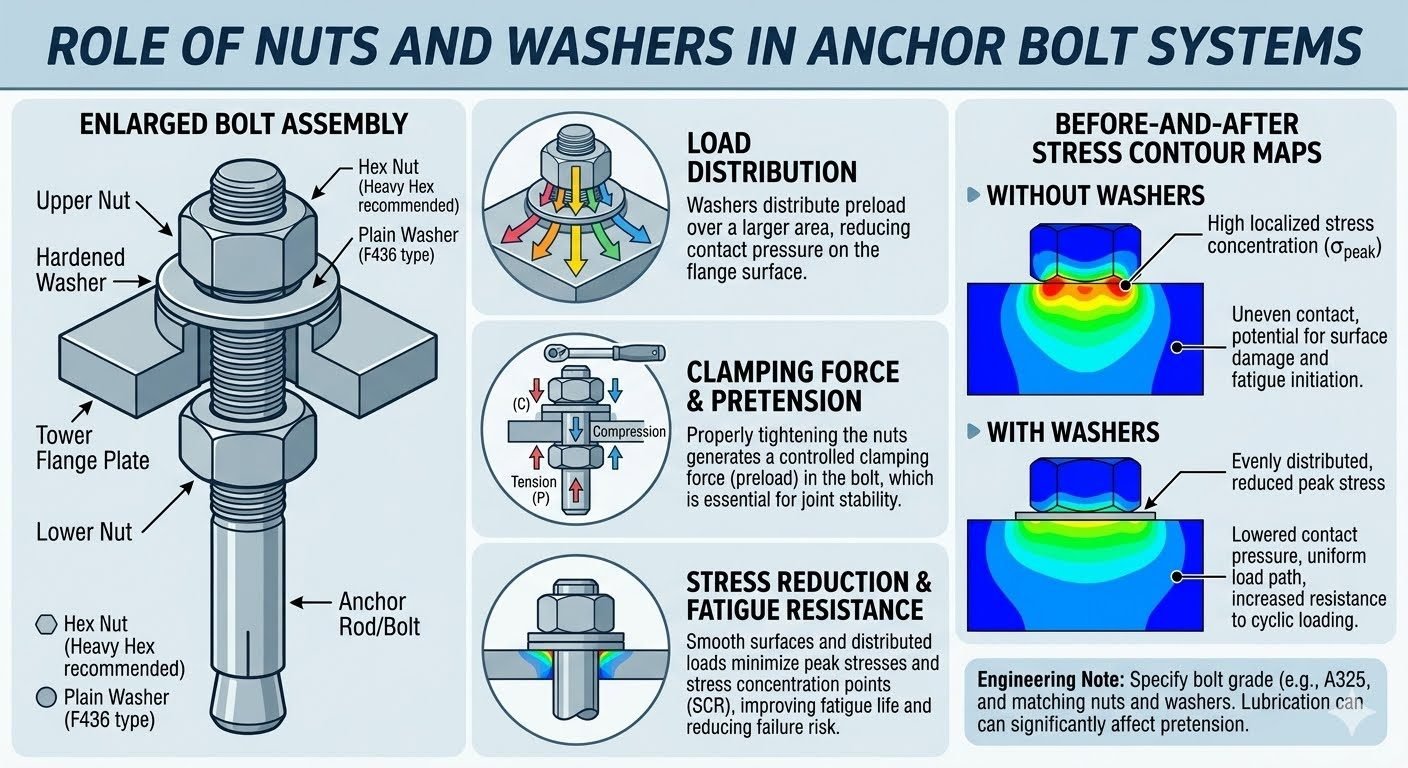
To achieve this, engineers utilize dual-ring configurations—an upper template ring and a lower anchor ring—fabricated from structural plate steel conforming to ASTM A572 Grade 50. These rings are CNC-machined to exact bolt-circle diameters, ensuring that every anchor bolt maintains uniform radial spacing. The high-strength anchor bolts, typically specified under ASTM A354 Grade BD or ASTM F1554 Grade 105, are pretensioned during assembly to lock the entire steel matrix into a pre-compressed state.
Fabrication Tolerances and Rigidity Parameters
During shop fabrication, the entire unit is assembled on a heavy-duty jig that simulates the tower flange geometry. Temporary bracing members are welded across the cage to maintain absolute squareness and prevent racking during transport and crane lifting. If the cage distorts by even a few millimeters across its diameter, the tower base flange will not seat flush, inducing catastrophic bending stresses into the threaded shanks upon final bolt tightening.
Weld procedures must comply with AWS D1.1 Structural Welding Code – Steel. All fillet and full-pen welds connecting the ring gussets and rebar tie-ins undergo mandatory magnetic particle testing (MT) or ultrasonic testing (UT) to detect subsurface inclusions or micro-cracks before dispatch to the job site.
Critical Design Warning: Thermal Expansion Mismatch
When massive structural steel anchor cages are embedded in deep concrete pours, hydration heat can cause internal core temperatures to spike above 70 degrees Celsius. Differential thermal contraction between the heavy steel rings and the curing concrete can induce severe thermal cracking if low-heat mix designs and internal cooling loops are not strictly engineered per ACI 207.2R guidelines.
Load Transfer and Concrete Bond Mechanisms
The primary function of the anchor cage is to transition tensile forces from the bolts into the compressive mass of the concrete foundation. This is accomplished through a combination of mechanical anchorage devices, such as welded anchor plates at the base of each bolt, and continuous bond stresses developed along the embedded anchor shank length.
The integrated rebar cage surrounding the anchor bolts acts as a confinement reinforcement grid, resisting bursting forces and preventing concrete cone breakout failures as defined in ACI 318 Chapter 17. Designers must ensure adequate development length and clear spacing between adjacent rebar layers to allow high-slump self-consolidating concrete (SCC) to completely encapsulate every structural member without forming honeycombs or voids.
Advantages
- Eliminates cumulative positioning errors by locking bolt patterns in a rigid shop jig.
- Drastically reduces on-site construction duration and crane hook-time in the excavation.
- Ensures superior weld quality and NDT inspection compliance in controlled factory environments.
- Provides a unified structural framework that safely resists handling and lifting stresses.
- Improves fatigue resistance under severe cyclic wind loads through precise coaxial alignment.
Disadvantages
- Demands specialized low-bed heavy transport permits due to oversized cage diameters.
- Requires high-capacity crawler cranes on-site for safe vertical lifting and maneuvering.
- Incurs higher upfront engineering and shop detailing expenses prior to foundation excavation.
- Provides zero tolerance for dimensional errors; any shop fabrication flaw requires complex rework.
- Demands meticulous staging space on remote wind farm sites to prevent structural distortion.
Onshore Utility-Scale Wind Farms
Standard onshore wind turbine generators ranging from 3MW to 7MW utilize massive gravity-base and piled foundations anchored by pre-assembled steel cages. These structures securely anchor tubular steel and hybrid concrete-steel towers against extreme atmospheric shear forces.
Offshore Fixed-Bottom Wind Foundations
Monopile and jacket transition pieces rely on heavy-duty bolted anchor flanges and internal stiffening cages. These components transfer severe wave-action bending moments and hydrodynamic loads from the superstructure into seabed-driven piles.
Heavy Industrial Tall Stacks and Masts
Industrial chimneys, flare stacks, and telecommunication lattice towers experience immense overturning moments identical to wind turbines. Utilizing pre-fabricated anchor cages ensures rapid, precise foundation installation for critical plant infrastructure.
Offshore Oil and Gas Platform Tie-Ins
Topside module support frames and drill rig substructures incorporate large-diameter structural anchor assemblies. These cages manage high-capacity tensile extraction loads under harsh marine environmental conditions without structural fatigue.
Anchor Cage Design Parameters and Dimensional Tolerances
Designing a high-capacity structural anchor cage requires rigorous adherence to dimensional tolerances to ensure proper load transfer between the wind turbine tower flange and the reinforced concrete foundation. In my experience on multi-megawatt onshore wind farms, even minor angular deviations during pre-assembly can translate into catastrophic bending moments at the base ring interface under cyclic fatigue loading. The data table below outlines the critical mechanical properties, dimensional tolerances, and material specifications enforced during shop fabrication and pre-assembly operations in accordance with ASME and ASTM standards.
Each parameter dictates a specific phase of quality control, ranging from the metallurgical grade of the threaded anchor rods to the micro-angular alignment of the upper and lower template rings. Review these thresholds carefully when establishing your quality assurance inspection checklists prior to the main foundation concrete pour.
| Parameter Description | Standard / Specification | Permissible Tolerance | Engineering Significance |
|---|---|---|---|
| Anchor Bolt Material Grade | ASTM A615 / ASTM A722 | Grade 75 / Gr. 150 min | Resists high tensile fatigue and dynamic shear reversals from turbine yaw. |
| Template Ring Flatness | ASME Y14.5 | Plus or minus 1.5 mm | Prevents uneven bolt pre-tensioning and localized stress concentration. |
| Bolt Circle Diameter (BCD) | ISO 13920-BF | Plus or minus 2.0 mm | Ensures frictionless mating with the manufactured wind turbine tower flange. |
| Vertical Plumbness | AWS D1.1 Structural Code | 1:500 overall height max | Eliminates parasitic bending moments in the embedded anchor rods. |
| Weld Classification | AWS D1.4 Rebar Welding | Full Penetration Groove | Maintains structural continuity of the integrated cage reinforcement network. |
*Note: All dimensional checks must be performed using calibrated laser total stations at an ambient temperature of 20 degrees Celsius to eliminate thermal expansion anomalies.
Technical Mapping & Specifications Matrix
To maintain absolute structural integrity across the entire design lifecycle, wind turbine foundation anchor cages are evaluated through a complex matrix of engineering entities, material designations, and quality verification protocols. In my professional practice, mapping these entities ensures that fabrication shops, site civil teams, and third-party inspectors speak a unified technical language. The matrix below bridges the physical components of the assembly with their governing standards and analytical functions.
By categorizing structural acronyms alongside their specific mechanical purposes, engineering teams can rapidly cross-reference compliance requirements during both shop audits and field erection sequences.
| Structural Entity | Primary Acronym | Governing Standard | Functional Specification |
|---|---|---|---|
| Anchor Cage Assembly | ACA-01 | IEC 61400-1 | Unifies bolts, rings, and rebar into a rigid transfer skeleton prior to concreting. |
| Bolt Circle Diameter | BCD | ASME B18.2.1 | Defines the precise radial pitch circle layout for tower connection bolts. |
| Upper / Lower Templates | ULT / LLT | AISC 360-16 | Maintains spatial geometry of anchor rods during transport and concrete pouring. |
| Fatigue Resistant Rebar | FRR-NET | ASTM A615 Gr. 80 | Absorbs cyclic shear forces and prevents concrete micro-cracking at the base. |
| Non-Shrink Grout Layer | NSG-SYS | ASTM C1107 | Provides ultimate compressive bearing support beneath the leveling flange. |
*Reference standard compliance must be verified via certified mill test reports (MTRs) before any welding or mechanical coupling commences on-site.
Site Verification Checklist for Anchor Cage Placement
Executing a flawless anchor cage installation requires a disciplined, multi-stage inspection protocol. Before permitting the concrete batch trucks to discharge into the foundation excavation, field quality engineers must sign off on every structural interface. Below is my field-tested checklist designed to eliminate alignment drift, structural deflection, and bonding failures during the pour.
Pre-Pour & Erection Verification Milestones
-
1. Foundation Excavation & Mud Mat Elevation Check:
Verify that the lean concrete mud mat is level within 5 mm across its diameter and cleared of all standing water and debris before cage lowering.
-
2. Pre-Assembly Shop Dimensional Audit:
Inspect bolt circle diameter (BCD), upper template ring flatness, and threading condition against ASME tolerances prior to crane lifting.
-
3. Rigging & Spreader Beam Integrity:
Confirm multi-point spreader beam rigging is balanced to prevent permanent plastic deformation of the steel cage during the lift.
-
4. Leveling Chair & Support Jack Stability:
Ensure heavy-duty leveling chairs welded to the lower cage are anchored securely to prevent settling under the dead weight of the cage and fresh concrete.
-
5. Vertical Plumbness & Azimuth Orientation:
Check total station laser readings to verify that the anchor bolts are plumb within 1:500 and the cable entry opening aligns precisely with the substation duct bank.
-
6. Rebar Bonding & Electrical Earthing Check:
Verify continuous electrical bonding across all welded rebar intersections and confirm adequate concrete cover blocks are installed on the cage exterior.
Adhering to this structured sequence guarantees that when the concrete pump commences operation, the anchor cage remains entirely immobilized and precisely aligned with design specifications.
Field Case Study: Real-World Application
During the construction of a 50-turbine wind farm in a high-wind coastal region, our engineering team encountered a severe alignment challenge during the installation of a 4.2-megawatt turbine anchor cage. Maintaining stringent tolerances under harsh site conditions tested our pre-assembly and leveling procedures to their absolute limits.
The Problem: Thermal Deflection and Differential Settlement
Unanticipated solar radiation during daytime pre-assembly caused thermal expansion across the upper template rings, resulting in a 4.5 mm out-of-tolerance drift in the bolt circle diameter before concrete placement.
- Ambient temperature swings exceeding 25 degrees Celsius between morning setup and afternoon placement.
- Inadequate temporary bracing between the upper and lower template rings during crane lifting.
- Minor ground subsidence beneath one of the heavy-duty leveling support chairs on the lean concrete mud mat.
- Potential rejection of the foundation ring by the turbine manufacturer due to severe bolt mating interference.
The Outcome: Precision Correction and Zero Defect Pour
By implementing an immediate corrective stabilization and shifting critical pours to nocturnal hours, the engineering team successfully restored total cage geometry and achieved full compliance with ASME standards.
- Installed hydraulic micro-jack assemblies to actively counteract thermal expansion forces in real time.
- Added diagonal tubular steel stiffeners to the internal cage skeleton, increasing torsional rigidity by 140 percent.
- Re-leveled the support chairs using high-strength steel shims verified by laser total station tracking.
- Completed the 350-cubic-meter mass concrete pour overnight with zero measurable post-placement displacement.
Engineering Recommendation: For all future large-scale anchor cage assemblies, mandate temperature-compensating surveying protocols and enforce rigid internal diagonal bracing whenever ambient thermal fluctuations exceed 15 degrees Celsius during installation windows.
Frequently Asked Engineering Questions
What is the primary function of an anchor cage in a wind turbine foundation?
The anchor cage functions as the primary structural load-transfer mechanism between the steel tower and the massive concrete gravity base.
- Transfers extreme overturning bending moments generated by dynamic wind shear.
- Anchors high tensile loads from cyclic fatigue forces via embedded threaded rods.
- Maintains absolute geometric tolerance prior to and during the mass concrete placement per ASCE standards.
How are anchor bolts tensioned within a pre-assembled steel cage?
Bolt tensioning is executed in strict sequence using calibrated hydraulic equipment to prevent uneven pre-load distribution across the flange.
- Employs multi-pass torque tightening protocols adhering to ASTM specifications.
- Utilizes hydraulic tensioners for large-diameter high-strength alloy steel rods.
- Measures bolt elongation directly with ultrasonic verification tools to confirm clamping force.
What are the key alignment tolerances during cage positioning?
Precise positioning is mandatory to ensure the tower base flange mates cleanly without inducing secondary bending stresses.
- Upper template elevation must remain within plus or minus 2 millimeters of design grade.
- Radial bolt pitch circle diameter verified using laser trackers before concrete release.
- Plumbness checked across multiple axes to eliminate eccentricity during grouting phases.
How does pre-assembly prevent differential settlement during concrete placement?
Rigid factory or site pre-assembly ties the entire steel skeleton together, locking relative element positions prior to fluid pressure loading.
- Welded and bolted intermediate rings resist lateral hydrostatic pressure from wet concrete.
- Integrated rebar lattice absorbs vibration from immersion needle vibrators without shifting.
- Temporary bracing members maintain structural squareness until full curing is achieved.
What corrosion protection methods are applied to buried anchor cages?
Long-term durability requires robust coating and sacrificial systems to withstand aggressive groundwater and chemical attack over 25 years.
- Application of heavy-duty fusion bonded epoxy coatings on exposed threaded sections.
- Cathodic protection integration via sacrificial zinc anodes in high-salinity soils.
- Rigid adherence to NACE guidelines for underground steel asset preservation.
Field Recommendation
Based on my two decades of field engineering experience managing heavy civil infrastructure projects, I advise project teams to enforce strict fabrication and handling controls for every wind turbine anchor cage installation.
- If site conditions involve aggressive, high-chloride soils or high water tables, mandate shop-applied fusion bonded epoxy coatings on all structural connection rings and verify dry-film thicknesses prior to foundation excavation release.
- If lifting large pre-assembled cages with a single crane, always employ a certified multi-point spreader beam assembly to limit dynamic deflection and prevent permanent out-of-round distortion of the upper template ring.
- If executing mass concrete pours around a complex rebar and bolt assembly, mandate slow-speed placement and symmetrical tremie pipe discharge to eliminate localized fluid pressure differentials that can rack the cage out of plumb.
- If verifying final dimensional compliance before concrete setting, utilize laser scanning over traditional optical leveling to capture full three-dimensional spatial data across every bolt pitch circle simultaneously.
Complete Course on
Piping Engineering
Check Now
Key Features
- 125+ Hours Content
- 500+ Recorded Lectures
- 20+ Years Exp.
- Lifetime Access
Coverage
- Codes & Standards
- Layouts & Design
- Material Eng.
- Stress Analysis
