How 5 Stakeholders Determine Wind Turbine Anchor Bolt Length
In my two decades managing heavy industrial foundations and wind energy infrastructure, I have observed that premature optimization of foundation dimensions frequently leads to severe structural bottlenecks. Establishing the correct anchor bolt length requires balancing extreme overturning moments, cyclic fatigue forces, and complex soil-structure interaction. No single engineering discipline possesses all the variables required to sign off on this dimension independently.
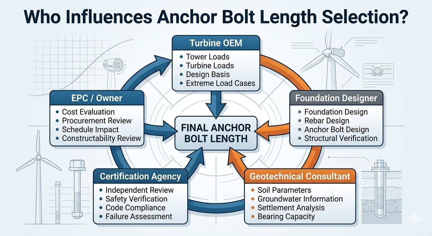
This multi-disciplinary reality demands a structured coordination matrix. Below, I break down how turbine manufacturers, structural designers, geotechnical consultants, independent certification bodies, and EPC contractors must synchronize their inputs to finalize this pivotal design parameter safely and economically.
Key Engineering Takeaways
- Anchor bolt length calculations directly govern load transfer from tower flanges into the reinforced concrete pedestal.
- OEM operational loads supply the dynamic force vectors, while geotechnical constraints dictate embedment depths.
- Independent certification agencies mandate rigorous safety verification before site pouring can commence.
- Commercial schedule and procurement reviews ensure threaded rod metallurgy remains constructible and cost-effective.
Stakeholder Integration in Anchor Bolt Length Design
Calculating the exact anchor bolt length is an exercise in multi-variable mechanics. The process begins with the Turbine OEM, who provides the ultimate aerodynamic thrust, rotor torque, and nacelle weight multipliers. These forces create extreme cyclic overturning moments at the tower base flange. According to ACI 318 and ASCE design guidelines, the tensile stresses induced by these moments must be fully developed into the foundation concrete without slip or pullout failure.
The Foundation Designer translates OEM loads into concrete section properties, rebar cage geometry, and anchorage layout. They apply anchorage-to-concrete breakout calculations, side-face blowout checks, and bond stress evaluations. However, the designer cannot finalize embedment without input from the Geotechnical Consultant. Soil stiffness, subsurface water tables, and bearing capacity directly dictate whether the foundation relies on a gravity base, rock anchors, or piled configurations, which in turn influences the pedestal height and overall bolt embedment profile.
Engineering Warning: Fatigue and Embedment Risks
Underestimating dynamic load amplification factors can lead to micro-gapping at the base joint, accelerating high-cycle fatigue in high-strength anchor assemblies. Ensure that prestress relaxation losses are explicitly factored into the total embedded length calculation to prevent premature bolt failure.
The Verification and Commercial Matrix
Once structural and geotechnical drafts are complete, the Certification Agency steps in to conduct independent reviews. They evaluate safety factors, extreme environmental load cases (such as 50-year wind gusts and seismic acceleration), and verify compliance with international standards like DNV-ST-0126. Their sign-off ensures that the proposed geometry will withstand operational fatigue limits over a standard 25-year design life.
Simultaneously, the EPC Contractor and Owner evaluate constructability and supply chain constraints. Extremely long bolts introduce transportation challenges, threading damage risks on site, and high material costs. The commercial team collaborates with structural engineers to optimize diameter versus embedment depth, ensuring that structural integrity is maintained while staying within project budget and schedule parameters.
Mathematical Framework for Embedment Development
The nominal embedment length (h_ef) is derived from concrete breakout capacity equations governed by tensile stress distribution:
- Tensile Force (N_ua): Maximum factored axial tension load transferred from the turbine tower wall per bolt.
- Concrete Compressive Strength (f’_c): Specified 28-day cylinder strength of the foundation pedestal mix.
- Basic Concrete Breakout Strength (N_b): Calculated using the constant factor multiplied by the square root of f’_c and h_ef^1.5.
- Modification Factors: Adjustments for cracked concrete, supplementary reinforcement, and edge distances.
By iteratively solving for h_ef where design resistance exceeds factored tension (phi N_n ≥ N_ua), the engineering team establishes the baseline anchor length. Any revision to turbine capacity or soil parameters instantly invalidates this equilibrium, requiring full re-evaluation across all five stakeholder groups.
Advantages of Multi-Party Design
- Holistic Risk Distribution: Shared input minimizes blind spots between structural, geotechnical, and mechanical domains.
- Enhanced Code Compliance: Dual-layer review by independent certification bodies guarantees adherence to global standards.
- Optimized Material Usage: Balancing OEM loads with actual soil capacity prevents over-design and excessive concrete consumption.
- Improved Fatigue Resistance: Rigorous joint verification reduces the likelihood of bolt loosening under continuous cyclic wind shear.
- Constructability Alignment: EPC involvement ensures chosen bolt lengths are physically transportable and installable on site.
Disadvantages and Challenges
- Prolonged Engineering Schedules: Coordinating five distinct stakeholder groups frequently extends the front-end design phase.
- Design Iteration Overhead: Minor adjustments in turbine nacelle weights trigger cascading recalculations across all teams.
- Conflicting Priorities: Commercial cost reduction goals can clash directly with conservative certification safety margins.
- Communication Bottlenecks: Misalignment between site geotechnical data and OEM load assumptions can halt procurement workflows.
- Administrative Complexity: Managing multi-party design sign-offs requires extensive document control and formal revision tracking.
Onshore Multi-Megawatt Wind Farms
Modern onshore turbines exceeding 5 megawatts generate unprecedented overturning moments. Foundation designers and OEMs collaborate closely to determine anchor bolt lengths that penetrate deep into reinforced octagonal gravity bases, ensuring safe load transfer without exceeding local concrete batching limits.
Offshore Transition Pieces and Monopiles
In marine environments, flange connections between monopiles and transition pieces rely on exceptionally robust stud bolts. Certification agencies and EPC contractors must account for marine corrosion allowances, wave slamming forces, and dynamic fatigue, requiring precise length adjustments to accommodate grouted sleeves and tensioning equipment clearance.
Complex Geotechnical Subsurface Sites
When wind farms are constructed on sloping terrain or marginal soils with high water tables, geotechnical consultants dictate deep micropile or driven pile configurations. The anchor bolt length must be integrated directly into the pile cap reinforcing cage to anchor the pedestal securely against differential settlement and seismic shear forces.
Turbine Repowering and Upgrades
Upgrading older 2MW tower locations with modern 4MW nacelles subjects existing concrete foundations to radically higher thrust loads. Independent certification bodies and structural engineers must evaluate whether existing anchor bolt lengths and steel cages can handle the upgraded loads or if extensive retrofit strengthening is mandatory.
Anchor Bolt Design Parameters and Stakeholder Input Matrix
Determining the final anchor bolt length requires an exhaustive reconciliation of conflicting parameters provided by multiple engineering disciplines. The table below outlines the specific data inputs, governing design codes, and responsible stakeholder groups that dictate sizing outcomes for onshore wind turbine foundations.
Each stakeholder contributes unique boundary conditions that directly influence embedment depth, tension development length, and fatigue resistance calculations under IEC 61400-1 extreme operating gusts. Review these inputs carefully to ensure no conflicting design assumptions exist between mechanical OEM loads and geotechnical capacity limits.
| Stakeholder Group | Primary Input Parameter | Governing Code / Standard | Impact on Bolt Length |
|---|---|---|---|
| Turbine OEM | Extreme overturning moments, shear forces, dynamic cyclic loads | IEC 61400-1 | Establishes baseline tensile force magnitude requiring minimum embedment and preload. |
| Foundation Designer | Concrete compressive strength, rebar congestion, load transfer mechanics | ACI 318-19 | Dictates concrete breakout cone dimensions and development length requirements. |
| Geotechnical Consultant | Soil shear strength, dynamic stiffness, groundwater table depth | ASTM D1586 / ISO 19901 | Influences pedestal stiffness and overall mass distribution affecting overturning resistance. |
| Certification Agency | Safety factors, independent finite element verification, fatigue verification | DNV-ST-0126 | Mandates safety margins that can force a 10% to 15% increase in nominal embedment. |
| EPC / Owner | Procurement lead times, material grade availability, crane pad scheduling | ASME Section VIII / Local Codes | Constrains maximum transportable bolt length and dictates standard threading configurations. |
Note: All parameters must be evaluated simultaneously during the Preliminary Design Review (PDR) phase to prevent costly re-engineering loops.
Technical Mapping & Specifications Matrix
To maintain absolute clarity across multidisciplinary teams, this matrix maps the core technical entities, structural acronyms, physical parameters, and hyperlinked standard references governing wind turbine foundation engineering.
Stakeholders must reference these standardized definitions during cross-functional design reviews to eliminate ambiguities in load path verification and material specification compliance.
| Entity / Acronym | Full Technical Description | Governing Parameter | Primary Reference Standard |
|---|---|---|---|
| PBL | Post-Tensioned Bolt Length | Total free length plus embedment depth | ASTM A615 |
| FEM | Finite Element Modeling | Stress concentration factor (SCF) at anchor flange | ISO 19902 |
| FOS | Factor of Safety against pullout | Minimum ratio of ultimate capacity to design load | ACI 318 |
| DLC | Design Load Case | Extreme operational and parked wind turbine states | IEC 61400-1 |
| GIR | Geotechnical Investigation Report | Soil bearing pressure and settlement modulus | ASTM D1586 |
System Integration Rule: Any modification to the Design Load Case (DLC) parameters triggers an automatic re-evaluation of the entire Finite Element Modeling (FEM) mesh and Geotechnical Investigation Report (GIR) boundaries.
Site Verification Checklist: Multi-Stakeholder Anchor Bolt Sign-Off
Anchor bolt length verification: Comprehensive quality assurance protocol ensuring all five stakeholder inputs are fully reconciled prior to concrete placement.
Executing complex renewable energy projects requires absolute synchronization between mechanical loading assumptions and civil constructability. Use this rigorous checklist on-site to verify that every stakeholder group has formally signed off on the final anchor bolt assembly dimensions, material grades, and embedment depths before any foundation pour commences.
Pre-Pour Stakeholder Sign-Off & Technical Validation Protocol
-
1. Turbine OEM Load Verification: Confirm that the latest foundation reaction loads from the turbine manufacturer (IEC 61400-1 DLC sets) match the design basis without un-notified engineering revisions.
-
2. Foundation Structural Design Audit: Verify that the foundation rebar cages and anchor bolt templates comply strictly with ACI 318-19 development length and concrete breakout calculations.
-
3. Geotechnical Parameter Cross-Check: Ensure soil bearing capacity, subgrade modulus, and groundwater table levels recorded on site align with the baseline ASTM D1586 geotechnical report.
-
4. Certification Agency Compliance Review: Validate that an independent third-party reviewer has issued a formal certificate of conformity for the structural calculations and fatigue analysis.
-
5. EPC Commercial & Logistics Sign-Off: Check that material procurement, bolt galvanization quality, and site crane pad scheduling comply with project budget and schedule constraints.
-
6. Final Combined Assembly Inspection: Conduct a joint site walk with representatives from all five stakeholder groups to sign the final anchor bolt release form before concrete truck dispatch.
By systematically checking off these six critical gateways, the engineering team eliminates latent defects, prevents costly foundation retrofits, and secures long-term structural integrity under severe operational fatigue conditions.
Field Case Study: Resolving Multi-Stakeholder Misalignment on Anchor Bolt Length
Multi-stakeholder misalignment: Real-world engineering crisis management during the construction of a 4.5 MW onshore wind farm in a complex geotechnical terrain.
During the construction phase of a major wind energy project, a severe disconnect between the turbine OEM and the geotechnical consultant threatened to derail the foundation installation schedule and compromise long-term structural safety.
Field Problem Analysis
The turbine OEM issued a sudden late-stage load revision increasing extreme overturning moments by 12 percent, which required an immediate recalculation of anchor bolt embedment depth.
- The foundation designer attempted to extend the anchor bolt length by 400 mm without consulting the geotechnical team regarding altered load transfer into the pile cap.
- The geotechnical consultant had previously identified a high water table and corrosive soil strata, meaning deeper embedment risked breaching a confining clay layer.
- The EPC contractor had already procured and delivered the original batch of anchor bolts to site, creating severe cost and schedule liabilities.
- The independent certification agency placed a hold on the construction permit due to the unverified discrepancy between mechanical loads and civil capacities.
Engineering Outcome & Resolution
A multidisciplinary emergency task force successfully harmonized all stakeholder requirements through an accelerated finite element analysis and cooperative commercial restructuring.
- The OEM provided refined operational sector management curves that reduced extreme fatigue peaks, allowing a moderated bolt length increase of only 150 mm.
- The foundation designer optimized the anchor chair geometry and high-strength concrete mix (ACI 318-19 Class F) to compensate for the shorter embedment without risking pullout failure.
- The geotechnical consultant approved local permeation grouting to seal the upper soil strata, mitigating corrosion risks near the extended bolt threads.
- The certification agency verified the revised design within 72 hours, enabling the EPC contractor to splice the existing bolts on-site without full re-procurement.
Final Recommendation: Always establish a formal change-management protocol at project kick-off. Designate the lead structural engineer as the central clearinghouse for any mechanical or geotechnical parameter updates to ensure all five stakeholder groups remain perfectly synchronized.
Frequently Asked Engineering Questions
Who holds the final contractual authority over anchor bolt length adjustments?
Contractual authority is distributed across multiple tiers, but changes ultimately require consensus sign-off.
How do extreme load cases from turbine OEMs alter embedment requirements?
OEM extreme load cases dictate the maximum tensile and shear fatigue envelopes for the anchorage.
- Higher bending moments at the tower flange require deeper embedment into the concrete mass.
- Cyclic fatigue loads necessitate precise steel prestressing calculations to prevent fatigue failure.
- Dynamic amplification factors directly expand the required pull-out resistance safety margins.
What geotechnical data parameters govern anchor bond length?
Subsurface conditions dictate how effectively loads transfer from the foundation block into the earth.
- Soil bearing capacity limits the allowable footprint and overall mass of the gravity base.
- Groundwater table depth affects buoyancy and long-term corrosion mitigation strategies.
- Settlement analysis profiles ensure differential movement remains within turbine tolerances.
Why is independent certification mandatory for wind turbine foundations?
Certification bodies provide neutral verification to satisfy investors, insurers, and local authorities.
- Independent reviews cross-check foundation designs against international standards like IEC 61400.
- Safety verifications protect against catastrophic overturning or pull-out failures.
- Failure assessments evaluate worst-case scenarios during extreme weather events.
How does constructability review influence bolt length specifications?
Theoretical structural lengths must be practical to manufacture, transport, and install on-site.
- Excessively long bolts create handling hazards and transport logistics challenges.
- Casting tolerances must account for rebar congestion within the foundation cage.
- Procurement reviews ensure material availability and cost-effective grade selection.
Field Recommendation
In my professional experience managing heavy civil scopes for wind energy installations, finalizing anchor bolt lengths requires rigorous cross-discipline alignment from day one. I advise project teams to implement the following actionable strategies to prevent costly redesigns:
- If geotechnical reports indicate high variability in soil stiffness across the turbine pad footprint, choose a conservative lower-bound bearing modulus to avoid underestimating anchor embedment depth.
- Establish a formal multi-party sign-off gateway early in the engineering phase, ensuring the EPC contractor, structural designer, and turbine OEM review load iterations simultaneously rather than sequentially.
- When transport or manufacturing limitations restrict single-piece bolt lengths, specify coupler systems backed by full-scale fatigue testing rather than risking unverified field splices.
- Mandate that the certification agency participates in early design reviews so that compliance deviations are identified before rebar cage fabrication begins on site.
Complete Course on
Piping Engineering
Check Now
Key Features
- 125+ Hours Content
- 500+ Recorded Lectures
- 20+ Years Exp.
- Lifetime Access
Coverage
- Codes & Standards
- Layouts & Design
- Material Eng.
- Stress Analysis
