Table of Contents
What is Pipe Stress Analysis? A Comprehensive Guide
Over my 20 years in the piping engineering field, I have seen many designs fail on paper before they ever reached the field. I remember a project in 2012 where a high-pressure steam line almost tore itself off its structural supports because the thermal expansion calculations were ignored. That is why pipe stress analysis is not just a step in the design process; it is the safeguard of your entire plant.
In this guide, I will walk you through the core principles of piping flexibility, the governing codes, and how we use modern software to prevent catastrophic failures. Whether you are a junior mechanical engineer or a seasoned project manager, understanding these fundamentals is key to delivering safe, reliable, and cost-effective piping systems.
Key Takeaways
- Understand the difference between sustained, occasional, and expansion loads.
- Learn how to apply ASME B31.3 code compliance rules to your designs.
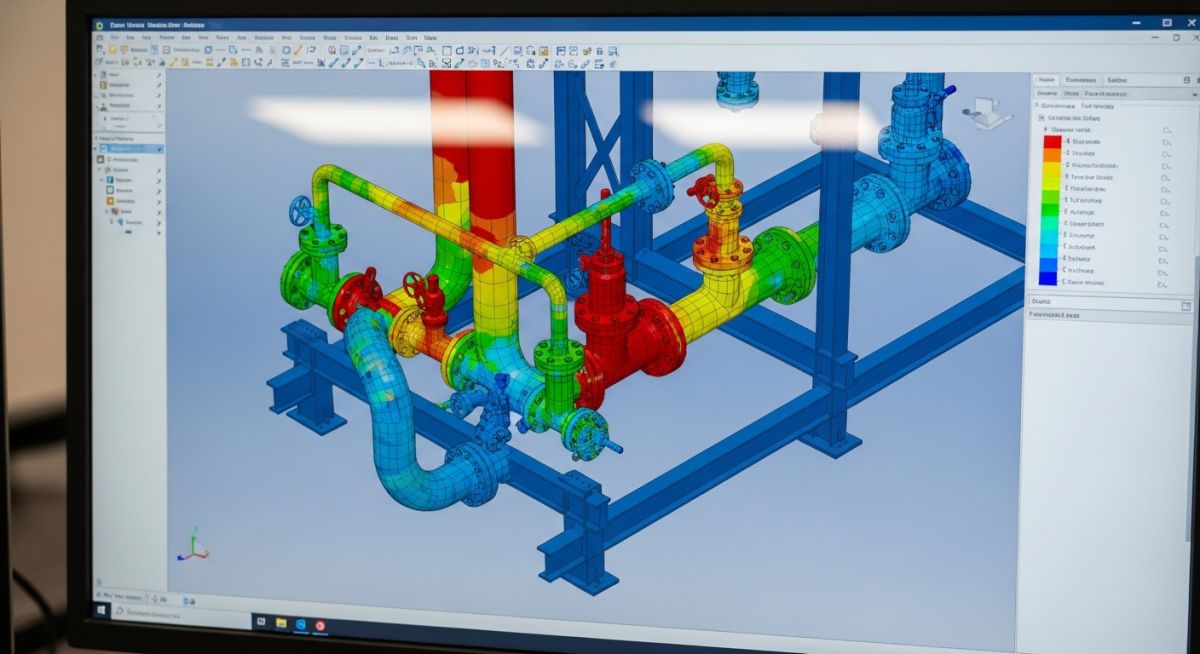
- Discover the role of modern stress analysis software like CAESAR II in engineering workflows.
Why Do We Perform Pipe Stress Analysis?
When a piping system is subjected to temperature changes, the metal expands or contracts. If this movement is restricted by anchors or supports, massive forces and moments are generated. These forces can easily buckle the pipe, damage expensive connected equipment like pumps and turbines, or cause flange joints to leak hazardous materials.
Primary vs. Secondary Stresses
In my practice, I categorize stresses into two main groups based on their behavior:
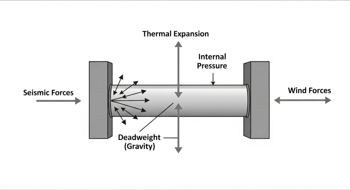
- Primary Stresses (Sustained and Occasional Loads): These are non-self-limiting stresses. They are caused by external mechanical loads such as internal pressure, deadweight of the pipe, fluid, insulation, and occasional loads like wind or seismic activity. If these stresses exceed the yield strength of the material, the pipe will undergo plastic deformation and fail.
- Secondary Stresses (Thermal Expansion Loads): These are self-limiting stresses. They are caused by the restriction of thermal expansion or contraction. As the pipe deforms, the local strain redistributes, which naturally limits the stress. However, cyclic thermal loading can lead to fatigue failure over time.
Governing Code Equations
To ensure safety, we design according to the ASME B31.3 Process Piping code. The code defines specific equations for calculating sustained and displacement stresses.
The sustained stress (S_L) due to pressure and weight must not exceed the hot allowable stress (S_h):
The displacement stress range (S_E) due to thermal expansion must not exceed the allowable displacement stress range (S_A):
How to Calculate Pipe Stress Analysis Limits
To perform accurate calculations, we must reference the material properties at both ambient (cold) and operating (hot) temperatures. Below is a reference table for common piping materials used in industrial plants, compiled from ASME B31.3 Appendix A.
| Material Spec | Common Name | Min Temp (°F) | Max Temp (°F) | Allowable Stress S_c (ksi) | Allowable Stress S_h @ 500°F (ksi) |
|---|---|---|---|---|---|
| ASTM A106 Gr. B | Carbon Steel | -20 | 800 | 20.0 | 18.9 |
| ASTM A312 TP304 | Stainless Steel | -425 | 1500 | 20.0 | 15.7 |
| ASTM A335 Gr. P11 | Low Alloy Steel | -20 | 1200 | 20.0 | 20.0 |
This matrix maps the core technical entities, structural acronyms, and physical parameters used during a typical stress analysis workflow.
| Entity / Parameter | Acronym | Primary Unit | Standard Reference | Description |
|---|---|---|---|---|
| Stress Intensification Factor | SIF (i) | Dimensionless | ASME B31.3 Appendix D | Fatigue correlation factor comparing piping components to straight pipe. |
| Modulus of Elasticity | E | Mpsi / GPa | ASME B31.3 Table C-6 | Measure of material stiffness at design temperature. |
| Thermal Expansion Coefficient | alpha | in/in/°F | ASME B31.3 Table C-1 | Rate of dimensional change per unit temperature change. |
Executing a Pipe Stress Analysis Checklist
Before finalizing any piping design or releasing isometric drawings for fabrication, I always run through a strict verification checklist. This ensures that the assumptions made in the software match the physical reality of the plant.
Design Verification Steps
-
✓
Design Parameters: Verify that design pressure, operating temperature, and fluid density match the process datasheet.
-
✓
Support Types: Ensure that anchors, guides, and spring hangers are modeled with correct stiffnesses and friction coefficients (typically 0.3 for steel-on-steel).
-
✓
Equipment Nozzle Loads: Check that calculated loads on pumps, vessels, and heat exchangers are within allowable limits specified by API 610 or ASME Section VIII.
-
✓
Flange Leakage: Perform flange leakage checks using the NC-3658 method or ASME Section VIII Division 1 Appendix 2 for critical high-pressure lines.
-
✓
Expansion Loops: Confirm that expansion loops have sufficient leg length to absorb thermal growth without exceeding allowable stresses.
Field Case Study: Real-World Application
The Problem: Flange Leakage on a High-Pressure Steam Line
During commissioning of a combined-cycle power plant, a 12-inch high-pressure steam line (operating at 750°F and 600 psi) experienced severe flange leakage at the steam turbine inlet nozzle. The initial design had passed basic flexibility checks, but the field installation did not account for the actual stiffness of the turbine connection. The resulting bending moments at the flange joint exceeded the allowable limits, causing the gasket to fail.
The Solution: Redesigning Support Configuration
I was called to the site to resolve the issue. We remodeled the entire system in CAESAR II, incorporating the exact nozzle stiffness values provided by the turbine manufacturer. To solve the problem, we:
- Replaced a rigid anchor near the turbine with a multidirectional guide.
- Added a spring hanger to support the deadweight of the vertical run without restricting thermal growth.
- Increased the length of the horizontal expansion loop by 6 feet.
These modifications reduced the bending moment at the turbine nozzle by 65%, bringing it well within the manufacturer’s allowable limits. The flange was retorqued, and the system has operated leak-free for over a decade.
Frequently Asked Engineering Questions
What is the difference between ASME B31.1 and ASME B31.3?
When is a formal computer-aided stress analysis required?
How do friction coefficients affect piping stress results?
What is a cold spring in piping design?
Why are spring hangers used instead of rigid supports?
What is the purpose of an expansion joint?
Complete Course on
Piping Engineering
Check Now
Key Features
- 125+ Hours Content
- 500+ Recorded Lectures
- 20+ Years Exp.
- Lifetime Access
Coverage
- Codes & Standards
- Layouts & Design
- Material Eng.
- Stress Analysis

📚 Recommended Resources: pipe stress analysis
Read these Guides
🎓 Advanced Training


Related posts:
![An engineer performing an API 579 fitness for service assessment on an industrial pressure vessel.]()
How to Perform API 579 Fitness for Service Assessment
![3D CAD render of a bolted flange joint assembly showing a compressed gasket.]()
Understanding Gasket m and y Factors in Flange Design
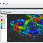
![PASS/START-PROF 4.86 pipe stress analysis software interface displaying a 3D piping model.]()
PASS/START-PROF 4.86 Released: Discover the New Pipe Stress Analysis Capabilities
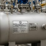
![ASME certification mark stamped on an industrial pressure vessel nameplate]()
What is ASME Certification? Procedure and Mark Explained
![Professional technician inserting a high-pressure hydro jetting nozzle into a sewer pipe cleanout.]()
What is Hydro Jetting and How Does It Work?
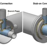
![Side-by-side comparison diagram of stub-in and stub-on piping branch connections.]()
Stub-in vs Stub-on Piping Connections: Engineering Design Guide