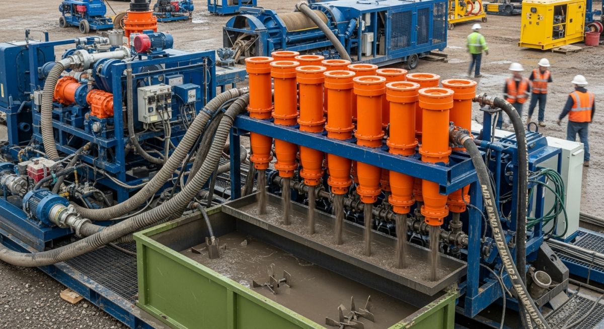
What is a Desander and How to Select One
In my 20 years of piping and process engineering, I have seen countless downstream pumps, valves, and heat exchangers completely destroyed by abrasive sand carryover. When high-velocity sand particles enter a piping system, they act like a continuous sandblasting operation from the inside out. This is where a desander becomes your primary line of defense.
Whether you are managing a drilling fluid system on an offshore rig, treating municipal wastewater, or protecting high-pressure injection pumps in an oilfield water flood project, understanding how to select, size, and operate a desander is a fundamental skill. Throughout my career, I have learned that successful solids control is not just about buying a piece of equipment; it is about matching the hydrocyclone geometry to your specific fluid dynamics and particle size distribution.
- Desanders target the separation of solids between 45 and 74 microns, bridging the gap between shale shakers and desilters.
- The system relies on centrifugal force generated by pressure drop, typically requiring a feed pressure of 30 to 45 PSI.
- Polyurethane and high-alumina ceramic are the preferred materials for hydrocyclone liners to resist extreme abrasive wear.
- Proper manifold design is critical to ensure equal flow distribution across multi-cone installations.
- Underflow monitoring is the most effective way to prevent “roping” and maintain separation efficiency.
How Does a Desander Work in Process Systems?
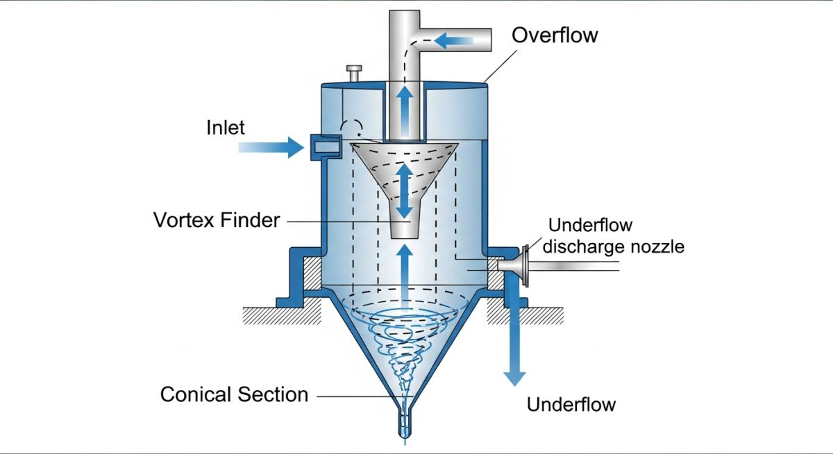
To understand a desander, we must look at the physics of a hydrocyclone. The fluid enters the hydrocyclone tangentially through an inlet nozzle at high velocity. This tangential entry forces the fluid into a rapid spinning motion, creating a primary vortex that travels downward along the inner wall of the cone.
As the fluid spins downward, centrifugal force drives the heavier solid particles outward toward the cone wall. These solids slide down the wall and exit through the apex opening at the bottom, often referred to as the underflow. Meanwhile, the clean fluid, which is less dense, forms an inner upward-spinning secondary vortex around a low-pressure core. This clean fluid exits through the vortex finder at the top of the cone, known as the overflow.
The Mathematics of Separation Efficiency
The separation efficiency of a hydrocyclone is characterized by its cut point, specifically the d50 cut point. This represents the particle size at which 50% of the particles are separated to the underflow and 50% remain in the overflow. In my design work, I use a modified version of Stokes’ Law to calculate this cut point:
Where:
- d50: Cut point particle diameter (microns)
- K: Empirical constant specific to the cone geometry and inlet design
- D_c: Inside diameter of the hydrocyclone cone (inches)
- viscosity: Plastic viscosity of the carrier fluid (centipoise)
- Q: Feed flow rate per cone (gallons per minute)
- rho_p: Density of the solid particles (grams per cubic centimeter)
- rho_f: Density of the carrier fluid (grams per cubic centimeter)
From this relationship, we can see that reducing the cone diameter (D_c) significantly decreases the cut point, allowing for the separation of much finer particles. This is why desanders typically use larger cones (8 to 12 inches) to target larger sand particles, while desilters use smaller cones (4 inches) to target finer silts.
In my field audits, I frequently observe desanders operating in a “roping” condition. Roping occurs when the solids concentration in the underflow is too high, causing the discharge to look like a solid, thick rope rather than a spray. This restricts the vortex finder’s low-pressure core, forcing heavy sand particles back up into the overflow. This completely defeats the purpose of the desander and rapidly destroys downstream piping. Always adjust the apex nozzle diameter to maintain a 20-to-30-degree spray angle.
Pressure Drop and Flow Rate Relationships
A hydrocyclone is a passive device; its separation energy comes entirely from the pressure drop across the unit. The relationship between pressure drop (Delta P) and flow rate (Q) is non-linear and can be expressed as:
Where C is a flow coefficient unique to the cone’s internal geometry. Operating below the recommended pressure drop (typically 30 PSI) results in insufficient centrifugal force, leading to poor separation. Conversely, operating above 45 PSI increases internal turbulence and accelerates abrasive wear on the cone walls without providing any meaningful improvement in separation efficiency.
Technical Specifications for Desander Selection
When selecting a desander for your piping system, you must match the physical dimensions of the cone to your process flow rate and target particle size. The table below outlines standard engineering parameters for industrial hydrocyclone cones operating under standard conditions.
| Cone Diameter (in) | Flow Capacity per Cone (GPM) | Operating Pressure (PSI) | d50 Cut Point (microns) | Typical Material of Construction |
|---|---|---|---|---|
| 8 | 200 – 250 | 30 – 35 | 45 – 55 | Polyurethane / Ceramic Liner |
| 10 | 400 – 500 | 32 – 40 | 55 – 65 | Polyurethane / High-Alumina Ceramic |
| 12 | 500 – 700 | 35 – 45 | 65 – 74 | Cast Iron / Polyurethane Lined |
Technical Mapping & Specifications Matrix
To ensure your desander installation complies with international standards, use this mapping matrix to align your design parameters with industry codes.
| System Component | Key Acronym / Parameter | Design Standard Reference | Critical Verification Rule |
|---|---|---|---|
| Manifold Piping | SDR / Schedule Rating | ASME B31.3 | Velocity must not exceed 4.5 m/s to prevent erosion. |
| Pressure Vessel Housing | MAWP (Max Allowable Working Pressure) | ASME Section VIII Div 1 | Must include a certified pressure relief valve (PRV). |
| Solids Separation | d50 Cut Point | API RP 13C | Testing must be performed using standardized silica sand. |
| Elastomeric Seals | Durometer / Polymer Type | ISO 13501 | Must be chemically compatible with drilling mud additives. |
Field Commissioning Checklist for Desander Units
Before you start up any desander system, you must perform a series of physical checks. In my experience, skipping these steps often leads to immediate system shutdown, damaged cones, or severe sand carryover that ruins downstream equipment.
-
Verify Manifold Alignment: Ensure that the inlet and outlet manifolds are perfectly aligned with no external piping stress transferred to the hydrocyclone bodies.
-
Inspect Apex Nozzles: Check that the apex nozzles are clear of debris and that the diameter matches the design flow rate and solids concentration.
-
Calibrate Pressure Gauges: Verify that pressure gauges are installed on both the inlet and outlet manifolds and that they are calibrated to within 1% accuracy.
-
Check Vortex Finder Depth: Confirm that the vortex finder is inserted to the correct depth inside the cone to prevent short-circuiting of feed fluid directly to the overflow.
-
Confirm Isolation Valve Operation: Test all isolation valves on individual cones to ensure they seal completely, allowing for online maintenance without shutting down the entire system.
Field Case Study: Real-World Application
At a geothermal drilling project in Nevada, the drilling fluid system was experiencing severe sand carryover. The centrifugal feed pumps supplying the high-pressure mud pumps were failing every 72 operating hours due to extreme impeller erosion. The existing 10-inch desander unit was in operation, but field measurements showed that the sand content in the active mud pits remained above 1.5% by volume, far exceeding the design limit of 0.1%.
I was called to the site to audit the system. Upon inspection, I found two major issues: first, the feed pump was oversized, forcing the desander to operate at an inlet pressure of 58 PSI, which caused severe internal turbulence. Second, the apex nozzles were completely worn out, leading to a “roping” discharge.
We replaced the worn polyurethane cones, installed smaller apex nozzles to restore the proper spray pattern, and installed a variable frequency drive (VFD) on the feed pump to maintain a steady inlet pressure of 35 PSI.
As a result, the sand content in the active mud pits dropped to 0.05% by volume. The service life of the centrifugal pump impellers increased from 72 hours to over 1,200 hours, saving the operator thousands of dollars in downtime and replacement parts.
This case highlights a critical lesson: a desander is only as good as its operating parameters. If you do not maintain the correct pressure drop and underflow geometry, even the most expensive system will fail to protect your downstream piping.
Frequently Asked Engineering Questions
What is the difference between a desander and a desilter?
How do I determine the correct feed pressure for my desander?
What materials are best for hydrocyclone liners?
Can a desander handle high-viscosity fluids?
What is “roping” and how do I fix it?
Which standards govern desander design and testing?
Complete Course on
Piping Engineering
Check Now
Key Features
- 125+ Hours Content
- 500+ Recorded Lectures
- 20+ Years Exp.
- Lifetime Access
Coverage
- Codes & Standards
- Layouts & Design
- Material Eng.
- Stress Analysis