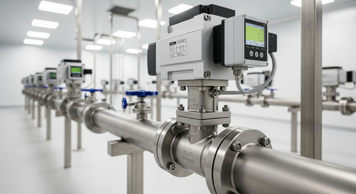
What are Modulating Valves? Types, Applications, and Benefits
In my 20+ years of commissioning petrochemical plants, I have seen countless systems fail simply because engineers treated control valves as simple on-off switches. When you are managing a high-pressure steam line or a volatile chemical feed, a standard gate valve won’t cut it. You need dynamic, real-time adjustments. That is where modulating valves come into play. I remember a project in 2014 where replacing a cycling on-off valve with a properly sized pneumatic modulating globe valve reduced our pressure fluctuations by 94% and saved the downstream turbine from catastrophic cavitation.
Unlike standard isolation valves that operate in a binary open-or-closed state, modulating valves position their internal trim anywhere between 0% and 100% open. This continuous adjustment is driven by an external controller, such as a PLC or DCS, which processes real-time sensor data and sends a variable signal (typically 4-20mA or 0-10V) to the valve actuator. This level of control is critical for maintaining system stability, optimizing energy efficiency, and preventing severe piping wear.
Key Engineering Takeaways
- Continuous positioning from 0% to 100% stroke allows for precise flow, pressure, and temperature regulation.
- Closed-loop feedback integration with PLC/DCS systems ensures rapid response to dynamic process changes.
- Minimization of water hammer and thermal shock significantly extends the service life of downstream piping.
- Compliance with ASME B16.34 and ANSI/FCI 70-2 leakage classes is mandatory for high-performance applications.
How Do Modulating Valves Regulate Flow?
To truly understand modulating valves, we must look at the physics of fluid dynamics. The primary parameter we calculate during design is the Valve Flow Coefficient (Cv). This coefficient represents the volume of water in US gallons per minute that will flow through a wide-open valve with a pressure drop of 1 PSI. For modulating applications, we do not just calculate a single Cv; we must map the Cv across the entire operating range of the system.
The fundamental equation for liquid flow through a control valve is:
Where:
Q = Flow rate in Gallons Per Minute (GPM)
SG = Specific Gravity of the fluid (water = 1.0)
dP = Pressure drop across the valve in PSI (P1 – P2)
In my field experience, the most common mistake is oversizing the valve. If a valve is oversized, it will modulate very close to its seat (typically below 10% open). This causes a phenomenon known as “seat hunting” or “wire drawing,” where high-velocity fluid rapidly erodes the plug and seat, leading to premature leakage and unstable control.
When modulating valves operate under high pressure drops, the localized pressure can drop below the vapor pressure of the liquid. This causes vapor bubbles to form (flashing). If the pressure recovers downstream, these bubbles collapse violently, generating micro-jets that can destroy hardened steel trim in a matter of weeks. Always calculate the cavitation index (sigma) using ISA-75.01.01 guidelines before finalizing your trim selection.
Trim Characteristics and Selection
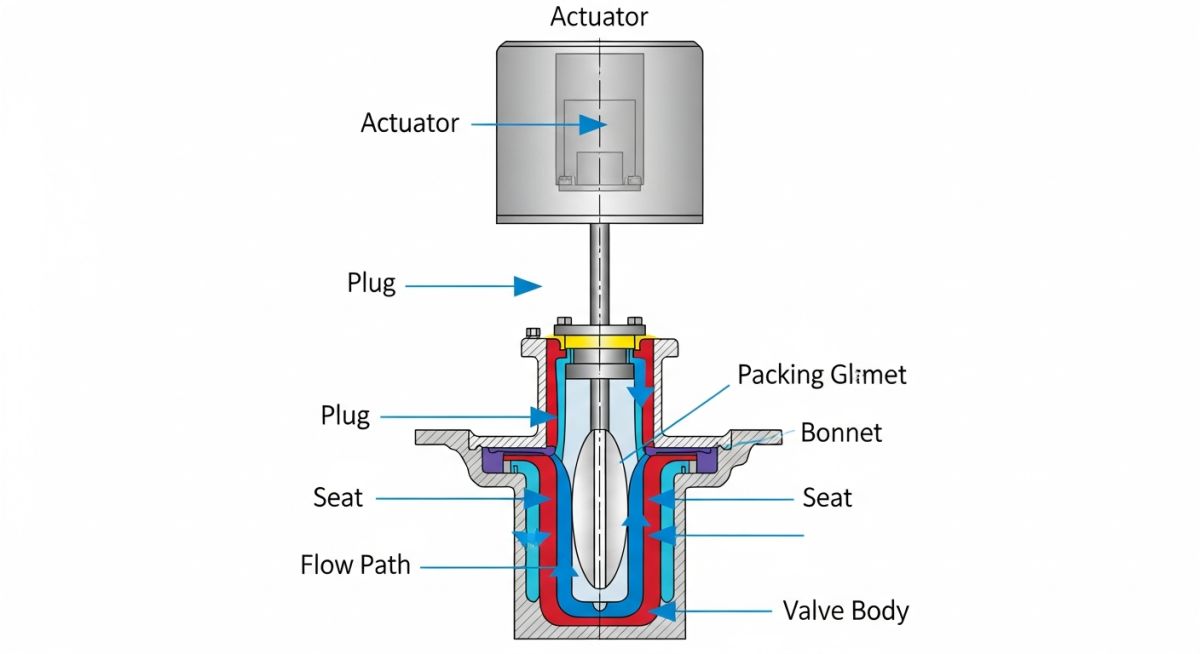
The relationship between valve lift and flow capacity is defined by the trim characteristic. There are three primary types used in modulating service:
- Equal Percentage: Equal increments of valve lift produce equal percentage changes in flow. This is the most common choice for systems where the pressure drop across the valve decreases as the flow rate increases.
- Linear: Flow rate is directly proportional to valve lift. This is ideal for systems with a constant pressure drop across the valve, such as liquid level control loops.
- Quick Opening: Provides maximum flow capacity immediately upon opening. This is rarely used for modulation and is typically reserved for on-off safety systems.
Different valve designs offer distinct advantages depending on the process conditions. The table below outlines the primary mechanical and operational differences between the most common modulating valve configurations used in heavy industry.
| Valve Type | Flow Characteristic | Pressure Recovery (FL) | Max Leakage Class | Typical Applications |
|---|---|---|---|---|
| Globe Valve | Linear / Equal % | High (0.85 – 0.90) | Class V / VI | High-pressure steam, boiler feedwater, precise chemical dosing |
| Segmented Ball | Equal % | Low (0.60 – 0.70) | Class IV | Slurries, fibrous pulp, high-flow gas systems |
| High-Performance Butterfly | Equal % | Low (0.55 – 0.65) | Class VI | Large diameter cooling water, low-pressure gas utility lines |
| Diaphragm Valve | Linear | Medium (0.75) | Class VI (Bubble-tight) | Corrosive chemicals, sanitary food/pharma processing |
To ensure compliance with international engineering standards, use this technical mapping matrix during the procurement and engineering design phases.
| Parameter / Entity | Standard Reference | Technical Definition | Engineering Significance |
|---|---|---|---|
| ANSI/FCI 70-2 | ANSI/FCI 70-2 | Control Valve Seat Leakage | Defines allowable leakage rates from Class I (highest) to Class VI (bubble-tight). |
| ASME B16.34 | ASME B16.34 | Valves – Flanged, Threaded, and Welding End | Governs pressure-temperature ratings, wall thickness, and material specifications. |
| ISA 75.25.01 | ISA 75.25.01 | Test Procedure for Control Valve Response | Establishes testing methods for step response and hysteresis in modulating service. |
| Hysteresis | IEC 60534-4 | Maximum difference in output for the same input | High hysteresis causes lag and oscillation in the control loop; must be kept under 1%. |
Before introducing process fluid into a newly installed piping system, the modulating valve assembly must undergo rigorous field verification. Skipping these steps often leads to erratic control loop behavior, packing leaks, or actuator damage during startup.
Field Verification Steps
-
Verify Flow Direction Arrow: Ensure the physical arrow cast on the valve body matches the actual process flow direction. Installing a globe valve backward can cause the plug to slam shut, causing severe water hammer.
-
Perform Actuator Calibration (Stroke Test): Input a 4mA (or 0%) signal and verify the valve is fully closed. Input a 20mA (or 100%) signal and verify full rated travel. Check intermediate steps (8mA/25%, 12mA/50%, 16mA/75%) to ensure linearity.
-
Inspect Instrument Air Supply: Verify that the pneumatic supply pressure matches the actuator nameplate rating (typically 35 to 60 PSI). Ensure the air is clean, dry, and filtered per ISA 7.0.01 standards.
-
Check Packing Gland Tightness: Adjust the packing gland nuts to the manufacturer’s specified torque. Over-tightening increases stem friction (stiction), which degrades modulating performance, while under-tightening causes fugitive emissions.
-
Confirm Positioner Feedback Loop: Verify that the digital positioner is communicating correctly with the DCS. Check that the analog output feedback signal matches the physical stem position within +/- 0.5% of span.
Field Case Study: Real-World Application
The Problem: Severe Cavitation and Piping Vibration
At a combined-cycle power plant, a high-pressure boiler feedwater pump bypass system was experiencing extreme vibration (exceeding 18 mm/s RMS) and loud, metallic popping noises resembling gravel flowing through the pipe. The original design utilized a heavy-duty on-off ball valve to dump excess flow back to the deaerator. Because the valve could not modulate, opening it caused an instantaneous pressure drop from 120 bar to 3 bar. This massive pressure drop triggered severe cavitation, which eroded the downstream piping wall thickness by 40% in less than six months of operation, threatening a catastrophic rupture.
The Solution: Multi-Stage Modulating Globe Valve
As the lead piping consultant, I recommended replacing the on-off ball valve with a pneumatic modulating globe valve equipped with a multi-stage, anti-cavitation trim (drilled-hole cage design). This trim splits the high pressure drop into four distinct, manageable stages, ensuring the localized fluid pressure never drops below the vapor pressure of the water. We integrated a smart digital positioner configured with an equal-percentage flow characteristic to match the pump’s performance curve.
The Outcome and Performance Metrics
The results were immediate and highly successful. By transitioning from binary on-off control to continuous modulation, we achieved the following improvements:
- Vibration Reduction: Piping vibration dropped from 18 mm/s to a safe level of 1.2 mm/s, well within ASME OM3 guidelines.
- Noise Mitigation: Near-field noise levels decreased from 104 dBA to 78 dBA, eliminating the need for expensive acoustic insulation.
- Process Stability: Deaerator level control stabilized, reducing pressure surges in the low-pressure steam system by 85%.
- Extended Asset Life: Ultrasonic thickness testing performed 12 months post-installation showed zero measurable wall loss in the downstream piping.
Frequently Asked Engineering Questions
What is the difference between a modulating valve and a control valve?
How do I prevent “stiction” in modulating valve actuators?
Why is an equal percentage trim preferred over linear trim in most applications?
What are the consequences of oversizing a modulating valve?
Can I use a standard ball valve for modulating service?
What is the role of a positioner on a modulating valve?
===FAQ_BLOCK===
Complete Course on
Piping Engineering
Check Now
Key Features
- 125+ Hours Content
- 500+ Recorded Lectures
- 20+ Years Exp.
- Lifetime Access
Coverage
- Codes & Standards
- Layouts & Design
- Material Eng.
- Stress Analysis
