What is a Vortex Breaker? Applications, Types, Design, and Working Principles
A Vortex Breaker is a critical mechanical internal component designed to prevent the formation of a fluid vortex when a liquid is drawn from a tank, pressure vessel, or separator. By disrupting the rotational flow patterns, this device ensures that gas or vapor entrainment does not occur, protecting downstream equipment like pumps from catastrophic failure due to cavitation.
Quick Definition: Vortex Breaker
A Vortex Breaker is a stationary piping component installed over a vessel outlet nozzle. Its primary function is to eliminate the “tornado effect” in draining liquids, preventing gas from being sucked into the outlet. This maintains a steady liquid flow, preserves Net Positive Suction Head (NPSH), and prevents pump cavitation in industrial processing.
Technical Knowledge Check
Test your understanding of vortex suppression and fluid dynamics.
Quiz Complete!
Complete Course on
Piping Engineering
Check Now
Key Features
- 125+ Hours Content
- 500+ Recorded Lectures
- 20+ Years Exp.
- Lifetime Access
Coverage
- Codes & Standards
- Layouts & Design
- Material Eng.
- Stress Analysis
The Physics of Fluid Swirl: Effect of Vortices on Flow Efficiency
In industrial fluid dynamics, a vortex occurs when a rotating motion of liquid is created around a central axis, typically during drainage through a bottom or side nozzle. This rotational kinetic energy creates a low-pressure zone at the core, often referred to as the air core. When the suction force exceeds the head of liquid, this core reaches the outlet, leading to gas entrainment.
Impact on Flow Dynamics and Flow Efficiency
The presence of an uncontrolled vortex significantly reduces Flow Efficiency. As gas is drawn into the liquid stream, the effective density of the fluid changes, causing erratic flow rates and pressure surges. In 2026, engineering simulations continue to show that even a small amount of entrained air (as low as 2% to 3% by volume) can reduce centrifugal pump efficiency by over 10%.

- Gas Ingestion: Leading to air-binding in pumps.
- Vibration: Mechanical stress on piping supports and internal vessel baffles.
- Reduced Head: Loss of discharge pressure in downstream systems.
Critical Applications of a Vortex Breaker in Industrial Systems
The installation of a Vortex Breaker is mandatory in systems where the liquid level fluctuates or where high-velocity discharge is required. These devices are standard in projects following ASME Section VIII or API 650 guidelines.
Refinery Fractionators
Used in bottom outlets to ensure 100% liquid phase enters the bottoms pump, preventing cavitation in high-temperature hydrocarbon service.
Storage Terminals
In large-scale storage tanks, a Vortex Breaker allows for maximum tank drawdown without risking air suction into the transfer line.
Fire Water Tanks
Ensures that fire-fighting pumps receive a steady, air-free water supply during emergency high-demand scenarios.
Engineering Standards for the Design of a Vortex Breaker
The Design of a Vortex Breaker is not a "one size fits all" process. Engineers must account for the nozzle diameter (D), the fluid velocity, and the Froude Number to ensure the device is sized correctly to suppress rotation.
ASME and API Design Considerations
While ASME Section VIII provides the structural framework for vessel internals, the hydraulic Design of a Vortex Breaker relies on empirical data. Common industry rules of thumb suggest:
| Parameter | Standard Specification |
|---|---|
| Baffle Width | Typically 2.0 to 4.0 times the nozzle diameter (D). |
| Clearance Height | Commonly D/2 above the nozzle opening to minimize pressure drop. |
| Material Selection | Must match vessel metallurgy (e.g., SS316L or Carbon Steel) per ASME requirements. |
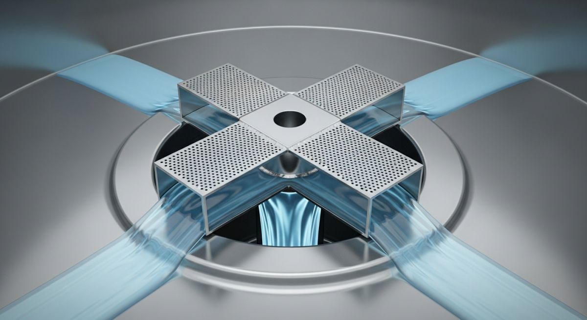
How It Works: The Mechanical Working of a Vortex Breaker
The Working of a Vortex Breaker is based on the principle of flow obstruction and streamline straightening. As fluid approaches an outlet, it naturally begins to rotate due to Coriolis forces or vessel geometry. The vortex breaker acts as a physical barrier that intercepts these tangential velocities.
The Mechanism of Flow Suppression
By forcing the fluid to pass through a series of plates or a mesh, the device converts the kinetic energy of the rotating fluid into a more stable, linear flow. This prevents the formation of a low-pressure core, ensuring that the liquid level remains flat even at high discharge velocities. This is essential for maintaining a constant NPSH during rapid vessel depressurization or drainage.
Classification and Primary Types of Vortex Breakers
Selecting the correct Types of Vortex Breakers depends on the vessel's orientation (vertical vs. horizontal) and the nature of the fluid.
| Type | Configuration | Best For |
|---|---|---|
| Cross-Plate Type | Four vertical plates welded in a "+" shape over the nozzle. | Standard process vessels and ASME Section VIII tanks. |
| Disk/Plate Type | A horizontal circular plate held by spacers above the nozzle. | Bottom outlets with limited vertical clearance. |
| Grating Type | A grid or honeycombed mesh structure. | High-velocity suction where minimal pressure drop is required. |
| Vane Type | Curved blades designed to counteract specific swirl directions. | Piping systems with pre-existing directional swirl. |
Improving NPSH: Vortex Breaker in Pump Suction Lines
Calculations for Critical Submergence
In 2026, engineers utilize the Froude Number (Fr) to determine when a Vortex Breaker becomes mandatory. The critical submergence depth (Sc) is the minimum liquid height above the nozzle required to prevent air ingestion.
Fr = v / (g * d)0.5
Where: v = Velocity (m/s), g = Gravity (9.81 m/s2), d = Nozzle Diameter (m)
If the calculated Froude Number exceeds 0.5, a Vortex Breaker in Pump Suction is highly recommended to protect the pump from cavitation. Cavitation occurs when the Net Positive Suction Head Available (NPSHA) falls below the NPSH Required (NPSHR) due to vapor entrainment.
- • Velocity Limit: Suction velocity should typically stay below 1.5 m/s for clean liquids.
- • Pressure Drop: The design must ensure the head loss through the breaker is less than 0.1 meters of liquid column.
Don't miss this video related to Vortex Breaker
Summary: Master Piping Engineering with our complete 125+ hour Certification Course: ......
Vortex Breaker Critical Submergence Calculator
Use this engineering tool to estimate the critical submergence depth (Sc) and the Froude Number for your nozzle. This helps determine if a Vortex Breaker is required to maintain pump NPSH.
Field Implementation: Solving Pump Cavitation with a Vortex Breaker
Project Data & Problem
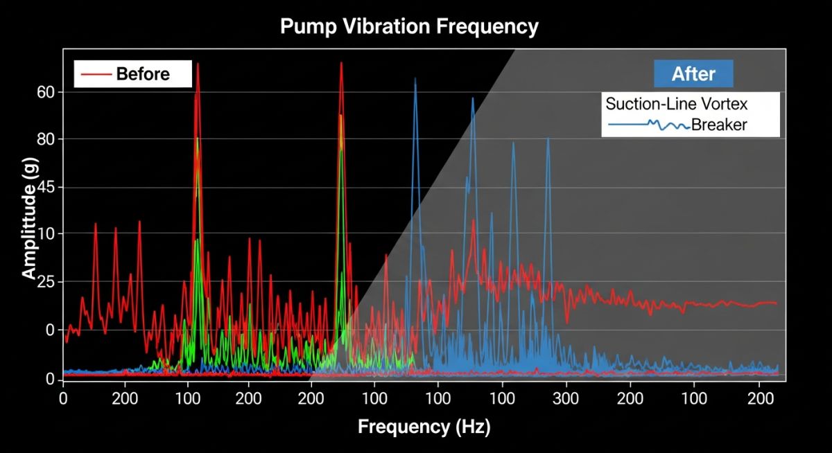
In a 2026 petrochemical expansion project, a vertical condensate receiver experienced severe vibration in the discharge pumps. Initial diagnostics showed the pump was operating within its NPSH envelope, yet vibration levels exceeded 12 mm/s RMS.
Failure Analysis
Engineering inspections revealed that as the liquid level dropped to 30% of the vessel height, a surface vortex formed. This "tornado" was entraining atmospheric nitrogen used for tank blanketing directly into the 8-inch suction nozzle. The resulting two-phase flow caused "gas locking" and impeller imbalance.
Engineering Fix
A stainless steel Cross-Type Vortex Breaker was retrofitted over the outlet nozzle. The design featured four blades at a 45-degree offset to the vessel shell to maximize the disruption of the tangential flow. The blades were sized at 3.0 times the nozzle diameter (24 inches wide).
Lessons Learned
- ✔️ Level alone does not prevent vortices; flow velocity is the primary driver.
- ✔️ Retrofitting a Vortex Breaker reduced pump vibration by 85%.
- ✔️ Proper ASME material matching prevents galvanic corrosion in internals.
Frequently Asked Questions: Vortex Suppression Engineering
How does a Vortex Breaker prevent Pump Cavitation? ▾
What are the ASME Section VIII requirements for vessel internals? ▾
Is a Vortex Breaker necessary in high-pressure separators? ▾
What is the impact of a high Froude Number on tank drainage? ▾
📚 Recommended Resources: Vortex Breaker
Read these Guides
🎓 Advanced Training
🎥 Watch Tutorials
 Understanding the Importance of Vortex Breakers in Piping Systems
 Vortex Breakers II Applications II Process Industry II EPCLAND
 Vortex Breakers II Effects of Vortices II Concepts II EPCLAND
 Vortex Breakers II Applications II Quiz II MCQs II Process Industry II EPCLAND
 Vortex Breakers II Concepts II Various Types II Comparison
 Vortex Breakers II Effects of Vortices II Quiz II MCQs II EPCLAND

Related posts:
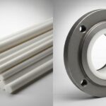
![Comparison of raw PTFE material and an industrial PTFE-lined steel pipe flange]()
Teflon vs PTFE: Major Differences in Industrial Piping Applications
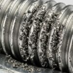
![Severe metal galling damage on a stainless steel threaded bolt and nut.]()
What is Metal Galling and How to Prevent It
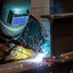
![Certified welder performing structural welding repair on a heavy steel beam with sparks flying.]()
Mastering Industrial Welding Repair Procedures for Structural Integrity
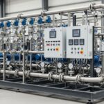
![A fully assembled industrial pump skid system with stainless steel piping and control panels in a factory.]()
What is an Industrial Pump Skid and Its Key Advantages?
![Side-by-side comparison of an industrial flow meter and a digital flow transmitter installed on a pipeline.]()
Flow Transmitter vs Flow Meter: Key Differences Explained
![Wireless vibration sensor mounted on an industrial electric motor for condition monitoring.]()
What is Vibration Monitoring and Why is it Important?