Table of Contents

How to Manage Technical Information Exchange With Process Equipment Vendors
In my 20-plus years of piping engineering, I have seen brilliant plant designs fall apart during construction for one simple reason: poor communication with equipment vendors. We spend months optimizing piping stress loops and structural steel frames, only to find out that the delivered skid has nozzle orientations rotated by 45 degrees or foundation bolt holes that miss the concrete piers by fifty millimeters. Managing the flow of technical data is not just an administrative task; it is the backbone of physical plant integration.
When we procure complex process packages—such as centrifugal compressor skids, water treatment units, or thermal oxidizers—we are not just buying hardware. We are buying information. If that information is late, inaccurate, or poorly integrated, the project schedule will slip, and engineering rework costs will skyrocket. Let us look at how to establish a bulletproof system to manage this exchange.
Key Takeaways for Project Engineers
- Establish a clear Vendor Document Register (VDR) with contractually binding review cycles.
- Freeze equipment nozzle loads and coordinates before finalizing piping stress analysis.
- Implement a strict interface control document (ICD) for all multi-discipline battery limits.
- Never release foundation designs for concrete pouring based on uncertified vendor drawings.
Complete Course on
Piping Engineering
Check Now
Key Features
- 125+ Hours Content
- 500+ Recorded Lectures
- 20+ Years Exp.
- Lifetime Access
Coverage
- Codes & Standards
- Layouts & Design
- Material Eng.
- Stress Analysis
Why Technical Information Exchange Fails on Major Projects
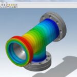
The primary failure point in vendor data integration is the reliance on “Preliminary” drawings for detailed engineering. In my experience, piping designers often route large-bore piping to a pump nozzle based on a first-pass vendor catalog drawing. If the vendor later changes the pump casing design to meet the specified NPSH (Net Positive Suction Head) requirements, the nozzle centerline may shift. This minor shift can invalidate weeks of piping stress analysis and spool fabrication.
The Engineering Rework Cost Calculation
To understand the financial impact of late or incorrect vendor data, we can model the engineering rework cost. Let us look at a scenario where a vendor changes the nozzle configuration on a high-pressure separator after the piping spools have been detailed:
Rework Cost Model:
Total Rework Cost = (N_spools * H_spool * R_eng) + (H_stress * R_eng) + (N_drawings * H_draft * R_eng)
Where:
• N_spools = Number of affected piping spools (e.g., 8 spools)
• H_spool = Engineering hours to redesign and detail each spool (e.g., 6 hours/spool)
• H_stress = Hours required to re-run piping stress analysis in CAESAR II (e.g., 16 hours)
• N_drawings = Number of affected isometric and GA drawings (e.g., 12 drawings)
• H_draft = Drafting hours to update and check each drawing (e.g., 4 hours/drawing)
• R_eng = Fully burdened engineering hourly rate (e.g., 85/hour)
Calculation:
Piping Redesign: 8 * 6 * 85 = 4,080
Stress Re-analysis: 16 * 85 = 1,360
Drafting Updates: 12 * 4 * 85 = 4,080
Total Engineering Rework Cost = 9,520 (Excluding physical fabrication scrap!)
This calculation demonstrates that even a minor change to a single equipment nozzle can cost thousands of dollars in engineering hours alone. If the piping has already been fabricated, the scrap and field modification costs can easily be ten times higher.
Best Practices for Technical Information Exchange With Package Vendors
To mitigate these risks, I recommend establishing a formal Interface Control Document (ICD) for every major equipment package. The ICD acts as a contract between the EPC team and the vendor, defining exactly who is responsible for what at the physical and functional boundaries.
For example, on a recent gas metering skid project, we defined the battery limit at the weld neck flange of the inlet manifold. The vendor was responsible for everything upstream of that weld, including the flange face finish and the gasket selection. Our piping team was responsible for the matching flange, bolting, and downstream piping. By documenting this interface in a signed ICD, we eliminated any ambiguity regarding the scope of supply and design responsibility.
How to Calculate Vendor Data Review Turnaround
Managing the timeline of document reviews is critical. If the engineering team takes too long to review vendor drawings, the vendor can claim a schedule extension and delay liquidated damages. The table below outlines a standard, high-performance document review matrix that I have used successfully on multi-million dollar projects.
| Document Code | Document Description | Review Priority | Target Turnaround (Days) | Critical Disciplines Involved |
|---|---|---|---|---|
| VDR-01 | General Arrangement & Footprint Drawings | High | 10 Days | Civil, Structural, Piping |
| VDR-02 | Nozzle Load & Coordinate Sheets | High | 10 Days | Piping Stress, Mechanical |
| VDR-03 | Piping & Instrumentation Diagrams (P&IDs) | Medium | 14 Days | Process, Instrumentation, Safety |
| VDR-04 | Electrical Single Line Diagrams | Medium | 14 Days | Electrical, Package Engineering |
| VDR-05 | Control Philosophy & Cause & Effect Matrix | Medium | 14 Days | Instrumentation, Process Control |
| VDR-06 | Welding Procedure Specifications (WPS) | Low | 21 Days | Materials, Quality Assurance |
Technical Mapping & Specifications Matrix
To ensure all engineering disciplines are aligned, we must map the core technical entities and their corresponding industry standards. This matrix serves as a quick reference for the engineering team during the vendor data review process.
| Equipment Category | Key Interface Parameter | Applicable Code / Standard | Critical Verification Check |
|---|---|---|---|
| Centrifugal Pumps | Nozzle Loads & Flange Ratings | API 610 / ISO 13709 | Verify that piping thermal expansion loads do not exceed Table 5 limits. |
| Pressure Vessels | Nozzle Projections & Orientations | ASME Section VIII Div 1 | Check nozzle clearance from vessel circumferential and longitudinal welds. |
| Shell & Tube Exchangers | Saddle Dimensions & Bolt Holes | TEMA / ASME VIII | Confirm slotted hole dimensions on the sliding saddle to allow thermal growth. |
| Skid Packages | Structural Lifting Lugs & COG | AISC 360 / BS EN 12079 | Verify Center of Gravity (COG) coordinates for safe crane lifting operations. |
How to Verify Vendor Interface Dimensions On-Site
Before any major equipment is set on its foundation, a rigorous field verification must be performed. I have developed this checklist over years of managing field installations to prevent the “it does not fit” scenario on-site.
Equipment Interface Field Verification Checklist
Verify Nozzle Coordinates and Elevations
Measure the actual nozzle centerlines against the certified “Approved for Construction” (AFC) drawings using a calibrated total station or laser scanner.
Check Flange Bolt Hole Orientation
Confirm that flange bolt holes straddle the natural centerlines in accordance with ASME B16.5. Misaligned bolt holes prevent piping connection.
Inspect Foundation Bolt Template
Compare the physical anchor bolt locations on the concrete foundation with the equipment baseplate hole dimensions before attempting to lower the equipment.
Validate Nozzle Face Flatness and Finish
Ensure the flange face roughness matches the specified gasket requirements (e.g., serrated spiral finish between 125 and 250 micro-inches AARH).
Confirm Electrical and Instrument Junction Box Locations
Verify that local junction boxes do not obstruct maintenance access ways or clash with nearby structural steel columns.
Field Case Study: Real-World Application
Field Case Study: Real-World Application
The Problem: The 120,000 Skid Alignment Clash
During a major refinery expansion project, a third-party vendor supplied a modular amine regeneration skid. The vendor’s mechanical team changed the skid’s structural base frame profile to accommodate a larger internal piping manifold. However, they failed to update the structural interface drawings sent to the EPC contractor.
When the 45-ton skid arrived on-site, the main structural beams clashed directly with the pre-poured concrete foundation piers. The anchor bolts were misaligned by 120 millimeters, making it impossible to set the skid. The construction crew was forced to halt work, leaving a heavy crane on standby at a cost of 15,000 per day.
The Outcome: Rapid Field Remediation and Process Redesign
As the lead piping engineer, I immediately organized an emergency technical alignment meeting. We laser-scanned the physical skid base and the concrete foundation to create an accurate 3D CAD model of the clash.
Instead of jackhammering the entire foundation, we designed a custom structural steel transition adapter plate. This plate bolted directly to the existing concrete anchor bolts and provided a new set of offset threaded studs that matched the revised skid base frame. The adapter plate was fabricated, non-destructively tested, and hot-dip galvanized within 72 hours.
While this solution saved the project schedule, the total cost of the adapter plate fabrication, engineering hours, and crane standby time reached 120,000. This entire expense could have been avoided if a strict technical information exchange protocol had been enforced.
Direct Recommendation: Implement a mandatory “Hold Point” in the project schedule. Do not allow the vendor to ship any equipment package until the EPC engineering team has received, reviewed, and signed off on the “As-Built” dimensional survey of the equipment baseplate and nozzle coordinates.
Frequently Asked Engineering Questions
What is the difference between “Certified” and “Preliminary” vendor drawings?
How do we handle vendor nozzle loads that exceed API 610 limits?
What is a Vendor Document Register (VDR) and why is it critical?
How do we manage interface changes on skid-mounted packages?
Who is responsible for the final alignment of rotating equipment?
How can we prevent communication gaps with international vendors?

📚 Recommended Resources: vendor technical information exchange
Read these Guides


Related posts:
![Industrial piping manifold showing different types of pipe joints including flanged and welded connections.]()
Mastering the Core Types of Pipe Joints in Industrial Piping
![CNC rotary draw tube bending machine shaping a stainless steel pipe in a manufacturing facility.]()
What is Tube Bending? Working, Types, and Industrial Applications
![Cross-section comparison of a metallurgically bonded clad pipe and a mechanically bonded lined pipe.]()
What is Cladded Pipe? Difference Between Clad and Lined Pipe
![3D piping stress analysis of a Smart Tee model in START-PROF software.]()
Mastering Smart Tee Model Considerations in START-PROF Stress Analysis
![Modern industrial compressed air system installation with rotary screw compressors and receiver tanks in a clean facility.]()
Designing a Compressed Air System for Maximum Industrial Efficiency
![Coated industrial bolts on an offshore pipeline flange showing corrosion protection.]()
Coating Selection for External Bolting to Reduce Corrosion in Piping