Vacuum Insulated Piping Systems: Engineering Design, Standards, and Performance for 2026
Vacuum Insulated Piping Systems represent the pinnacle of cryogenic fluid management, designed specifically to transport liquids at temperatures as low as -269°C with minimal thermal degradation. As global demand for LNG, hydrogen, and semiconductor cooling scales in 2026, understanding the mechanical integrity and thermodynamic efficiency of these systems is critical for EPC architects and process engineers.

What are Vacuum Insulated Piping Systems?
Vacuum Insulated Piping Systems (VIPS) are dual-walled conduits consisting of an inner process pipe and an outer vacuum jacket. The annular space is evacuated to high vacuum levels and filled with Multi-Layer Insulation (MLI) to virtually eliminate heat transfer via conduction, convection, and radiation during the transfer of cryogenic fluids.
Table of Contents
- Core Applications of Vacuum Insulated Piping Systems
- Technical Advantages vs. Conventional Insulation
- Structural Classification and Types
- Engineering Specifications and Materials
- Thermodynamic Comparison and Heat Leak Analysis
- Mechanical Integrity and ASME B31.3 Compliance
- Installation Standards and Bayonet Technology
- Leading Global Manufacturers in 2026
- Maintenance and Vacuum Integrity Protocols
Cryogenic Engineering Knowledge Check
Question 1 of 5
Complete Course on
Piping Engineering
Check Now
Key Features
- 125+ Hours Content
- 500+ Recorded Lectures
- 20+ Years Exp.
- Lifetime Access
Coverage
- Codes & Standards
- Layouts & Design
- Material Eng.
- Stress Analysis
Core Applications of Vacuum Insulated Piping Systems in Modern Industry
As we progress through 2026, the reliance on Vacuum Insulated Piping Systems has expanded beyond traditional laboratory settings into massive industrial infrastructures. These systems are essential for maintaining the liquid state of cryogens during transit, where even a slight thermal gain could result in catastrophic pressure spikes or product loss.
- Green Hydrogen Economy: Distribution of Liquid Hydrogen (LH2) at -253°C from liquefaction plants to heavy-duty refueling stations.
- Aerospace Propulsion: Transfer of Liquid Oxygen (LOX) and Liquid Methane (LCH4) to launch pad storage tanks for orbital delivery systems.
- Semiconductor Fabrication: High-purity Liquid Nitrogen (LN2) delivery for ultra-cold wafer processing environments.
- Life Sciences: Cryogenic preservation in bio-banks and the distribution of medical-grade oxygen in advanced healthcare facilities.
Technical Advantages of Vacuum Insulated Piping Systems vs. Conventional Insulation
The primary driver for selecting Vacuum Insulated Piping Systems over traditional foam-insulated piping (such as Polyurethane or Aerogel) is the order-of-magnitude reduction in heat leak. While traditional insulation relies on material thickness to slow heat transfer, vacuum technology eliminates the medium required for conduction and convection entirely.
| Performance Metric | Foam-Insulated Pipe | Vacuum Insulated Piping Systems |
|---|---|---|
| Heat Leak (Watts per Meter) | 15.0 – 25.0 | 0.5 – 2.0 |
| Service Life | 5 – 10 Years (Moisture Degradation) | 20 – 30 Years (Stainless Steel) |
| External Temperature | Often shows condensation/frost | Ambient/Dry |
| Installation Footprint | Large (Thick Insulation Layers) | Compact (Minimal Diameter Increase) |
Structural Classification: Types of Vacuum Insulated Piping Systems
Design engineers classify Vacuum Insulated Piping Systems based on their physical flexibility and the permanence of the installation. In 2026, modularity has become a key design trend to reduce field-labor costs.
Rigid Vacuum Insulated Piping (RVIP) for Permanent Installations
Rigid systems consist of straight sections and pre-fabricated elbows. They offer the highest thermal efficiency and are typically used in long-distance transfer lines where structural rigidity is required to support heavy valve manifolds. These systems are designed in accordance with ASME B31.3 Process Piping codes to handle high-pressure cryogenic loads.

Flexible Vacuum Insulated Piping (FVIP) for Complex Routing
Flexible variants utilize a corrugated inner and outer bellows-style construction. This allows for easier installation in tight spaces, such as inside ship hulls or semiconductor cleanrooms. Flexible Vacuum Insulated Piping Systems are also excellent for absorbing vibration from pumps or accommodating thermal expansion without the need for complex expansion loops.
Engineering Specifications for Vacuum Insulated Piping Systems
The design of Vacuum Insulated Piping Systems is governed by strict mechanical standards to ensure safety and longevity in extreme environments.
Material Selection: 304/316L Stainless Steel Requirements
Austenitic stainless steels are the materials of choice for 2026 cryogenic projects. Type 304 is standard for the outer jacket, while Type 316L is often specified for the inner process pipe when dealing with corrosive environments or high-purity requirements. These materials maintain excellent Charpy V-notch impact toughness at temperatures down to -269°C.
Vacuum Level Maintenance and Getter Technology
Maintaining a static vacuum over a 20-year lifespan requires advanced chemical “getters” and molecular sieves. These materials are placed inside the vacuum annulus of Vacuum Insulated Piping Systems to adsorb out-gassed molecules from the metal surfaces and any microscopic helium leaks that may occur over time.
Thermodynamic Analysis: Heat Leak Minimization in Vacuum Insulated Piping Systems
The efficiency of Vacuum Insulated Piping Systems is quantified by the rate of heat ingress from the ambient environment into the cryogenic process stream. In 2026, engineering teams utilize the Modified Fourier Law to calculate radial heat transfer across the vacuum annulus. Because gas conduction and convection are eliminated by the high vacuum (typically below 10-4 Torr), radiation becomes the dominant heat transfer mechanism.
Thermodynamic Heat Leak Formula:
Q = (2 × 3.14159 × keff × L × (Tambient – Tcryogenic)) / ln(router / rinner)
Where Q is the heat leak in Watts, keff is the effective thermal conductivity of the MLI (Multi-Layer Insulation), and r represents the radii of the jacket and process pipes.
Mechanical Integrity: Thermal Contraction and ASME B31.3 Compliance
One of the most significant engineering challenges for Vacuum Insulated Piping Systems is managing the drastic thermal contraction of the inner pipe. When Liquid Nitrogen (LN2) piping is chilled from 20°C to -196°C, stainless steel contracts by approximately 3 millimeters per meter of length.
To maintain ASME B31.3 compliance, designers must incorporate internal bellows or expansion loops. These components absorb the DeltaL change without compromising the vacuum seal of the outer jacket. Failure to properly calculate these stresses can lead to buckling of the inner pipe or catastrophic fatigue failure of the vacuum jacket welds.
| Cryogen Type | Boiling Point (°C) | Contraction (mm/m) | Recommended Piping |
|---|---|---|---|
| Liquid Oxygen (LOX) | -183 | 2.8 | Rigid VJP |
| Liquid Nitrogen (LN2) | -196 | 3.0 | Rigid or Flexible |
| Liquid Hydrogen (LH2) | -253 | 3.2 | Advanced MLI Rigid |
| Liquid Helium (LHe) | -269 | 3.3 | He-Shielded Systems |
Installation Standards: Bayonet Joints and Cryogenic Transfer Connection
Modern Vacuum Insulated Piping Systems often utilize “Bayonet” connections to join pipe spools. A bayonet is a male-to-female mechanical joint with a long, close-tolerance interface.
- Frost-Free Operation: The long thermal path ensures the sealing O-ring remains at near-ambient temperature, preventing ice buildup.
- Field Modularity: Bayonets allow for the rapid assembly of Vacuum Insulated Piping Systems without the need for complex vacuum pumping in the field.
- Alignment Sensitivity: Precision engineering is required to ensure that the inner pipe remains concentric during the cooling phase to avoid “thermal shorts” (metal-to-metal contact).
Leading Global Manufacturers of Vacuum Insulated Piping Systems
As of 2026, the market for Vacuum Insulated Piping Systems is dominated by specialized cryogenic engineering firms that provide turn-key EPC solutions. Notable leaders include:
- Chart Industries: Recognized for large-scale LNG and hydrogen infrastructure.
- Vacuum Barrier Corporation: Specialists in LN2 dosing and semiconductor fluid transfer.
- Acme Cryogenics: Known for custom-engineered field-welded and bayonet systems.
- Demaco: A European leader in high-end superconducting magnet cooling systems.
Long-Term Maintenance Protocols for Vacuum Insulated Piping Systems
While these systems are designed for a 25-year lifespan, vacuum degradation is the most common failure mode. Maintenance protocols in 2026 involve annual vacuum level checks via integrated “thermocouple gauge” ports. If a “soft vacuum” is detected (rising above 10-2 Torr), the system may require “re-evacuation” using a high-vacuum turbo-pump station to restore thermal performance.
Vacuum Insulated Piping Systems Heat Leak Calculator
Estimate the thermal performance of your cryogenic transfer line. This tool calculates the estimated heat ingress (Watts) and liquid boil-off rates based on 2026 engineering benchmarks for high-vacuum systems.
Note: Calculations are based on typical 2026 performance data for Vacuum Insulated Piping Systems with a vacuum level of 10-4 Torr and 40 layers of MLI.
Case Study: Eliminating LH2 Boil-off in Aerospace Vacuum Insulated Piping Systems
In early 2026, a major aerospace launch provider experienced significant liquid hydrogen (LH2) losses during pre-launch propellant loading. The existing transfer lines were experiencing excessive ice formation at joint interfaces, indicating a critical failure in the thermal barrier.
Project Data
- Fluid: Liquid Hydrogen (LH2)
- Operating Temp: -253° Celsius
- System Length: 450 Meters
- Initial Loss Rate: 18% Boil-off per hour
Failure Analysis
Thermal imaging and vacuum decay tests revealed "soft vacuum" conditions (10-1 Torr) caused by microscopic stress cracks in the internal expansion bellows. These cracks were traced to improper support spacing that failed to account for the extreme Vacuum Insulated Piping Systems contraction during rapid chill-down cycles.
The Engineering Fix
The engineering team replaced the compromised sections with high-performance Vacuum Insulated Piping Systems featuring "Smart Bayonet" technology. Key upgrades included:
- Dynamic Support Systems: Specialized PTFE-lined rollers to allow the jacket to remain stationary while the inner pipe contracts.
- Enhanced Getters: Utilization of advanced Palladium-based hydrogen getters within the vacuum annulus to maintain long-term integrity.
- ASME B31.3 Stress Validation: Full FEA (Finite Element Analysis) re-validation of all field-welded vacuum jacket seams.
Lessons Learned
This project demonstrated that for hydrogen-service Vacuum Insulated Piping Systems, the selection of internal bellows materials and the precision of bayonet machining are non-negotiable. Post-installation boil-off was reduced to less than 1.5% per hour, resulting in operational savings exceeding 250,000 USD per launch cycle.
FAQ: Engineering Insights into Vacuum Insulated Piping Systems
What is the typical service life of Vacuum Insulated Piping Systems in 2026? ▼
How do Vacuum Insulated Piping Systems manage extreme thermal contraction? ▼
Is field welding necessary for the installation of Vacuum Insulated Piping Systems? ▼
What vacuum level is considered optimal for high-performance cryogenic transfer? ▼
Conclusion: Maximizing Efficiency with Vacuum Insulated Piping Systems
In 2026, the transition toward high-efficiency cryogenic logistics makes Vacuum Insulated Piping Systems an indispensable asset. By minimizing boil-off rates and providing frost-free operation, these systems protect both the product and the surrounding infrastructure.
Successful implementation requires a holistic approach that includes rigorous material selection, adherence to ASME B31.3 piping codes, and the use of modern monitoring technology. As industrial demands for liquid hydrogen and high-purity nitrogen grow, Vacuum Insulated Piping Systems remain the gold standard for thermal performance and operational reliability.
📚 Recommended Resources: Vacuum Insulated Piping Systems
Read these Guides

Related posts:
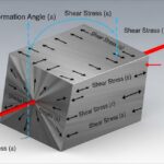
![3D engineering diagram illustrating shear modulus deformation on a solid block with force vectors.]()
Understanding Shear Modulus and Modulus of Rigidity in Piping Design
![3D render of a protective chromium oxide film forming on a stainless steel surface.]()
How Does Stainless Steel Oxide Film Formation Prevent Corrosion?
![Side-by-side comparison of industrial metal casting and metal forging processes.]()
Casting vs Forging: Key Differences for Industrial Piping Systems
![Various types of industrial pumps displayed in a modern engineering facility.]()
Guide to Types of Pumps and Their Working Principles
![3D digital GIS map overlay showing petroleum pipeline routes across a terrain]()
Why GIS in Petroleum and Pipeline Industry is Absolutely Critical
![CAESAR II Version 14 pipe stress analysis software interface displaying a 3D piping model.]()
What Is New in CAESAR II Version 14 Pipe Stress Analysis