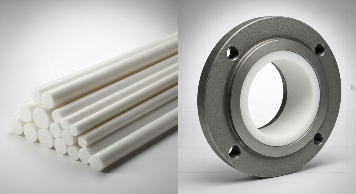
Teflon vs PTFE: Major Differences in Industrial Piping Applications
In my 20-plus years of piping engineering, I have sat in countless project alignment meetings where clients, procurement managers, and junior engineers debated whether to specify “Teflon” or “PTFE” for their corrosive chemical lines. I always start by clearing up the confusion: chemically, they are the same compound. However, from a practical procurement and quality control standpoint, the distinction is highly significant.
When we design high-integrity piping systems for hot sulfuric acid, wet chlorine, or aggressive solvents, we rely on the unique properties of Polytetrafluoroethylene. Whether you source it as generic PTFE or under the brand name Teflon, understanding how this material behaves under pressure, vacuum, and thermal cycling is what prevents catastrophic field failures.
Key Engineering Takeaways
- Chemical Identity: PTFE is the chemical name of the polymer; Teflon is the brand name owned by Chemours (originally DuPont).
- Design Standards: Lined piping systems must comply with ASTM F1545 to ensure liner integrity.
- Thermal Limits: Both materials operate reliably from -29°C up to 260°C, but mechanical strength drops rapidly above 120°C.
- Venting Requirements: Because of gas permeation, all PTFE-lined carbon steel pipes require venting holes to prevent liner collapse.
- Vacuum Limitations: Unreinforced PTFE liners can easily collapse under vacuum conditions at elevated temperatures.
Understanding Teflon vs PTFE in Chemical Process Piping
To understand the mechanical behavior of these materials, we must look at their molecular structure. PTFE is a high-molecular-weight polymer consisting entirely of carbon and fluorine atoms. The carbon-fluorine bond is one of the strongest single bonds in organic chemistry, which gives the material its near-total chemical inertness and low coefficient of friction.
Manufacturing Methods: Paste Extrusion vs Isostatic Molding
In my experience, the method used to manufacture the liner is far more critical than the brand name stamped on the shipping crate. For piping liners, two primary methods are used:
- Paste Extrusion: Used primarily for straight pipe runs. Fine powder PTFE resin is mixed with an extrusion aid, compressed into a preform, and extruded through a die. This creates highly oriented polymer chains, offering excellent longitudinal tensile strength but making the liner susceptible to radial splitting if not handled carefully.
- Isostatic Molding: Used for complex fittings like tees, elbows, and custom reducers. PTFE powder is compressed under equal pressure from all directions inside a mold, then sintered. This produces isotropic mechanical properties, meaning the liner resists stress equally in all directions.
Permeation and Thermal Expansion Calculations
Two physical phenomena dominate the design of PTFE-lined piping systems: gas permeation and thermal expansion mismatch.
1. Gas Permeation Rate Calculation
No polymer is completely gas-tight. Highly corrosive gases like chlorine, hydrogen chloride, and wet sulfur dioxide will slowly migrate through the molecular gaps in a PTFE liner. The permeation rate can be calculated using the following plain-text formula:
Where:
Q = Permeation rate (cm3/second)
P = Permeation coefficient of the specific gas through PTFE
A = Surface area of the pipe liner (cm2)
delta_p = Partial pressure gradient of the gas across the liner (atm)
L = Liner wall thickness (cm)
By increasing the liner thickness (L) from 3mm to 5mm, we can cut the permeation rate in half. This is why I always specify heavy-wall liners for high-permeation services, regardless of whether the client requests generic PTFE or brand-name Teflon.
2. Thermal Expansion Mismatch
The linear thermal expansion coefficient of PTFE is roughly ten times higher than that of carbon steel.
PTFE Thermal Expansion: alpha = 120.0 x 10^-6 m/m/K
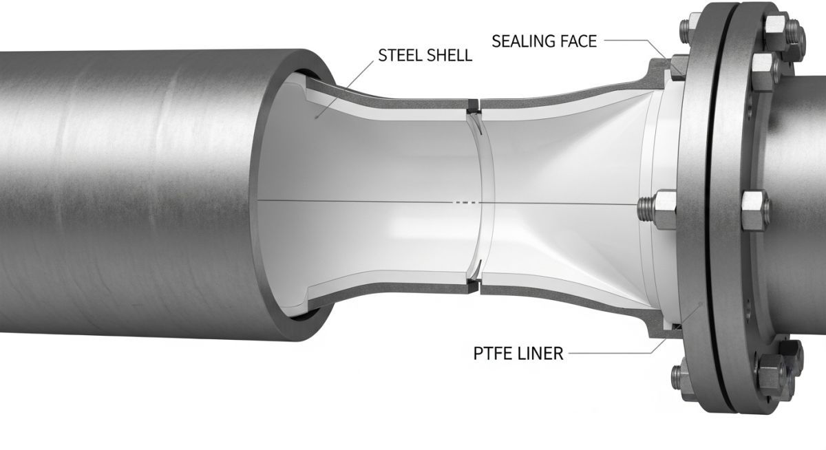
When a lined pipe is heated from ambient temperature to 150°C, the liner wants to expand ten times more than the surrounding steel shell. Because the liner is locked in place by the flared faces at the flanges, this thermal expansion creates massive compressive stress. If the liner is not properly processed, it will buckle inward, leading to flow restriction or localized stress cracking.
Never use standard PTFE-lined piping in full vacuum services at temperatures exceeding 120°C without consulting the manufacturer’s vacuum rating charts. The combination of thermal expansion softening and external vacuum pressure will cause the liner to collapse inward, completely blocking the process flow and tearing the flared faces.
The following data table outlines the mechanical limits of virgin PTFE resins used in piping liners manufactured under ASTM F1545. These values must be verified during material receiving inspections.
| Property | Test Method | Value (Metric) | Value (Imperial) |
|---|---|---|---|
| Density | ASTM D792 | 2.14 – 2.19 g/cm³ | 133.6 – 136.7 lb/ft³ |
| Tensile Strength (Min) | ASTM D4894 | 21 MPa | 3045 psi |
| Elongation at Break (Min) | ASTM D4894 | 250% | 250% |
| Thermal Conductivity | ASTM C177 | 0.25 W/m·K | 1.7 BTU·in/hr·ft²·°F |
| Coefficient of Friction | ASTM D1894 | 0.05 – 0.10 | 0.05 – 0.10 |
| Max Operating Temp | Process Limit | 260°C | 500°F |
This matrix maps the core technical entities, structural acronyms, and standard references required when writing specifications for fluoropolymer-lined piping systems.
| Entity / Acronym | Full Technical Name | Primary Standard Reference | Application Scope |
|---|---|---|---|
| PTFE | Polytetrafluoroethylene | ASTM D4894 | Base resin specification for raw molding and extrusion powders. |
| PFA | Perfluoroalkoxy Alkane | ASTM D3307 | Melt-processible fluoropolymer used for complex injection-molded fittings. |
| FEP | Fluorinated Ethylene Propylene | ASTM D2116 | Lower temperature limit (150°C) fluoropolymer used for less aggressive services. |
| ASME B31.3 | Process Piping Code | ASME B31.3 | Governs the design, pressure ratings, and testing of the outer metallic shell. |
| ASTM F1545 | Standard Specification for Plastic-Lined Ferrous Metal Pipe | ASTM F1545 | Defines qualification, testing, and dimensional requirements for lined assemblies. |
Evaluating Teflon vs PTFE Lined Pipe Field Installation
During my time supervising field installations, I have seen more PTFE liners ruined during the construction phase than during actual plant operations. Because PTFE is a relatively soft plastic, it is highly vulnerable to mechanical damage before and during bolt-up.
The flared face of the liner acts as its own gasket. If a construction worker uses a standard metal piping alignment tool or drops a flange face onto concrete, the sealing surface is ruined, and the entire spool must be scrapped.
PTFE Lined Piping Installation Checklist
-
Flange Face Protection: Keep the protective wooden or plastic covers bolted to the spool flanges until the exact moment of installation. Never use a utility knife to trim flared faces.
-
Vent Hole Verification: Ensure every single straight spool has at least two vent holes (typically 2mm to 3mm diameter) drilled through the steel shell. Verify these holes are clear of paint, insulation, or debris.
-
Torque Limit Compliance: Use a calibrated torque wrench. Tighten bolts in a star pattern in 30% increments up to the manufacturer’s specified maximum torque. Over-torquing will crush and cold-flow the PTFE flare, causing a leak path.
-
No Welding Near Liners: Absolutely no welding, cutting, or grinding is permitted on the steel shell once the PTFE liner has been inserted. The localized heat will instantly melt the fluoropolymer.
-
Electrostatic Grounding: For flammable solvent services, verify that grounding studs are welded to the steel shell and that continuity jumpers are installed across all flanged joints to prevent static buildup inside the non-conductive liner.
Field Case Study: Real-World Application
The Problem: Catastrophic Liner Collapse in Sulfuric Acid Service
At a chemical processing facility in Texas, a 4-inch carbon steel piping system lined with generic PTFE was carrying 98% sulfuric acid at 140°C. During a routine process shutdown, the line was blocked in while still hot. As the acid cooled, it created a localized vacuum inside the pipe.
Within hours, the operator noticed a sudden drop in downstream flow upon restart. Upon inspection, we discovered that the PTFE liner had completely collapsed inward, folding like a soda straw. The plant had specified standard-wall PTFE without verifying the vacuum rating at elevated operating temperatures, and the vent holes had been painted over during construction, trapping permeated gas in the annulus.
The Outcome: Engineering Redesign and Remediation
I was brought in to lead the failure analysis. We implemented a three-part engineering solution:
- Heavy-Wall Isostatic Liners: We replaced the collapsed spools with heavy-wall, isostatically molded PTFE liners compliant with ASTM F1545, which increased the vacuum rating at 140°C from 150 mmHg to full vacuum.
- Spiral Venting System: We specified spools with spiral venting grooves machined into the inner steel wall, leading to open vent studs. This allowed any permeated acid gas to escape safely to the atmosphere rather than building up pressure behind the liner.
- Strict Torque Protocols: We retrained the mechanical crew on torque limits and mandatory star-pattern tightening, preventing cold-flow deformation at the flange faces.
The redesigned system has now been operating for over five years without a single leak or flow restriction.
My direct recommendation for any high-temperature, corrosive service is to never treat PTFE-lined piping as a commodity item. Always specify the liner thickness, the resin grade, the manufacturing method (paste extruded vs isostatic), and verify that the venting system is fully functional before commissioning.
Frequently Asked Engineering Questions
Is there any chemical difference between Teflon and PTFE?
Why do PTFE-lined pipes have vent holes in the steel shell?
What is the maximum operating temperature for PTFE-lined piping?
Can you weld on a pipe spool that has already been lined with PTFE?
How does PTFE compare to PFA for lined fittings?
Why is torque control so critical during the installation of lined pipes?
===FAQ_BLOCK===
Complete Course on
Piping Engineering
Check Now
Key Features
- 125+ Hours Content
- 500+ Recorded Lectures
- 20+ Years Exp.
- Lifetime Access
Coverage
- Codes & Standards
- Layouts & Design
- Material Eng.
- Stress Analysis

