Learn what a globe valve is, how it works, its key parts, common types, and standard symbols in this comprehensive engineering guide.
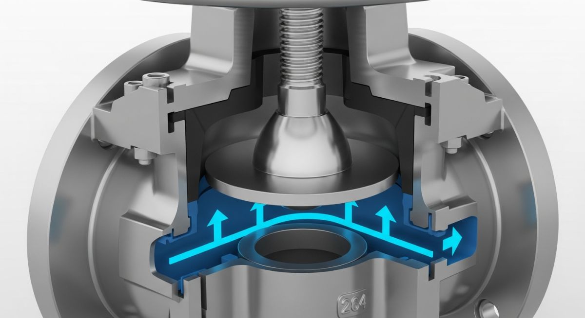
Learn what a globe valve is, how it works, its key parts, common types, and standard symbols in this comprehensive engineering guide.
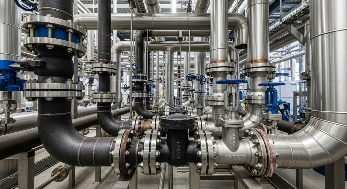
Learn how to select the right metallic pipe materials for industrial applications, covering carbon steel, stainless steel, and alloys.
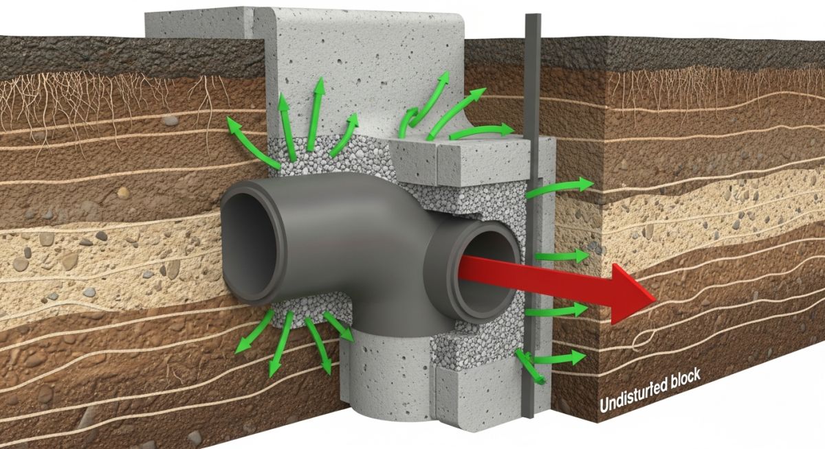
Learn what a thrust block is, its design, construction, types, working principles, and how it differs from an anchor block in piping systems.
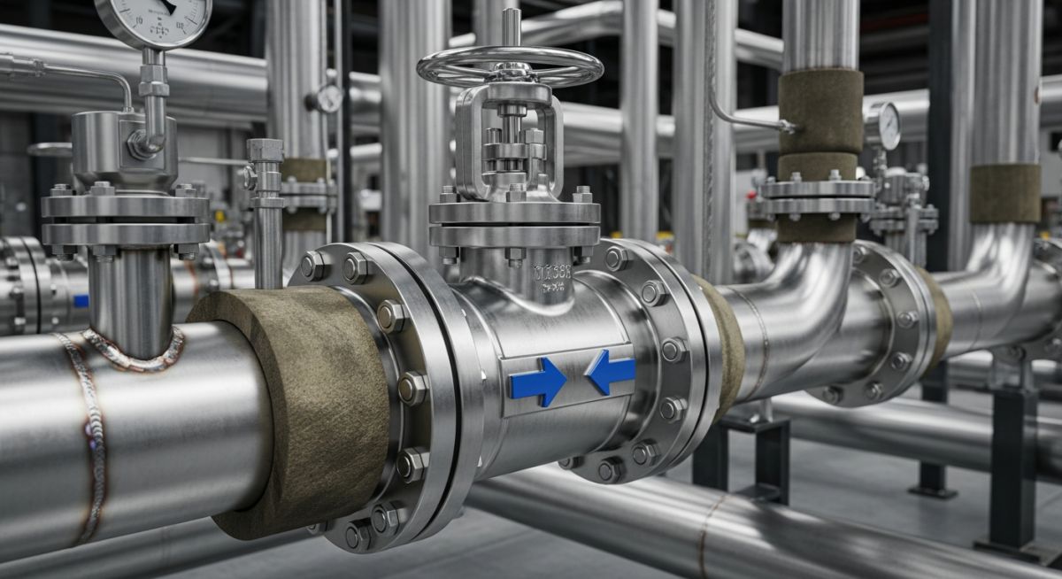
Learn what a non-return valve (NRV) is, how it works, its various types (swing, lift, ball), and standard engineering symbols.

Master industrial piping design with the best online piping engineering courses taught by industry experts. Advance your engineering career today!
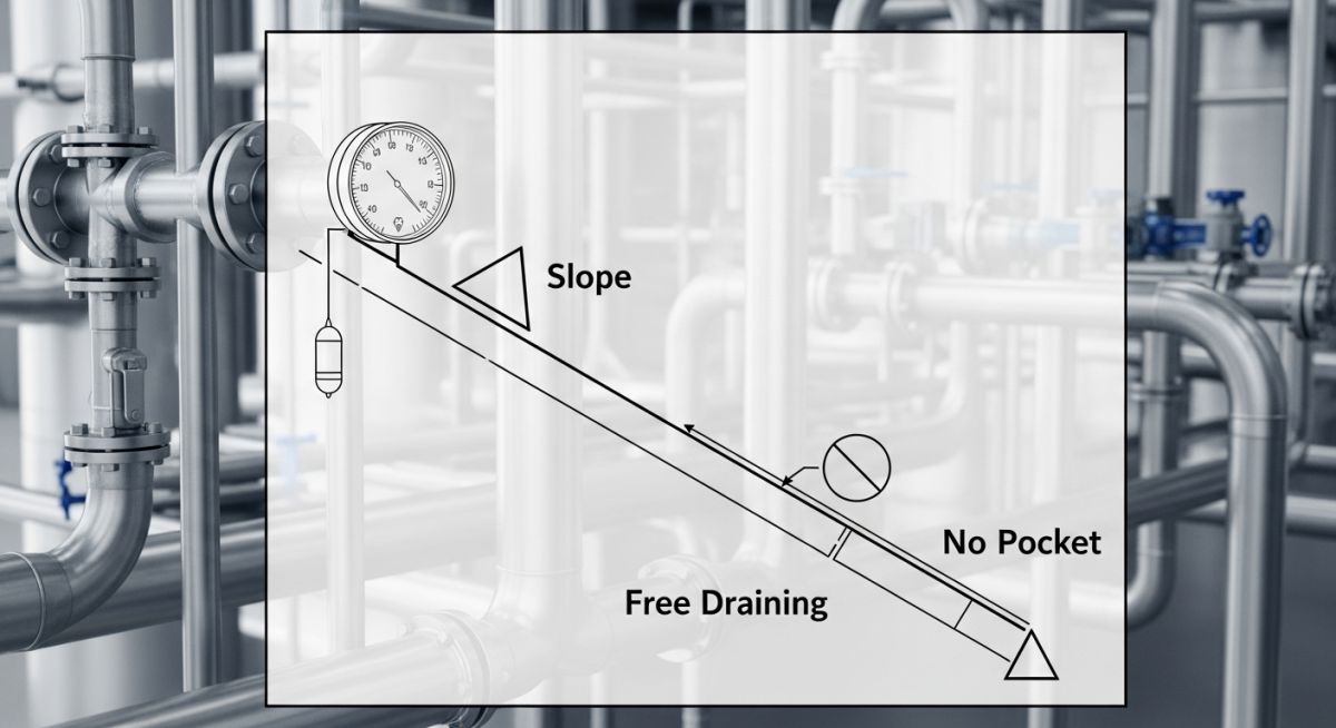
Learn the critical differences between slope, free draining, gravity flow, and no pocket piping requirements in P&ID schematics.
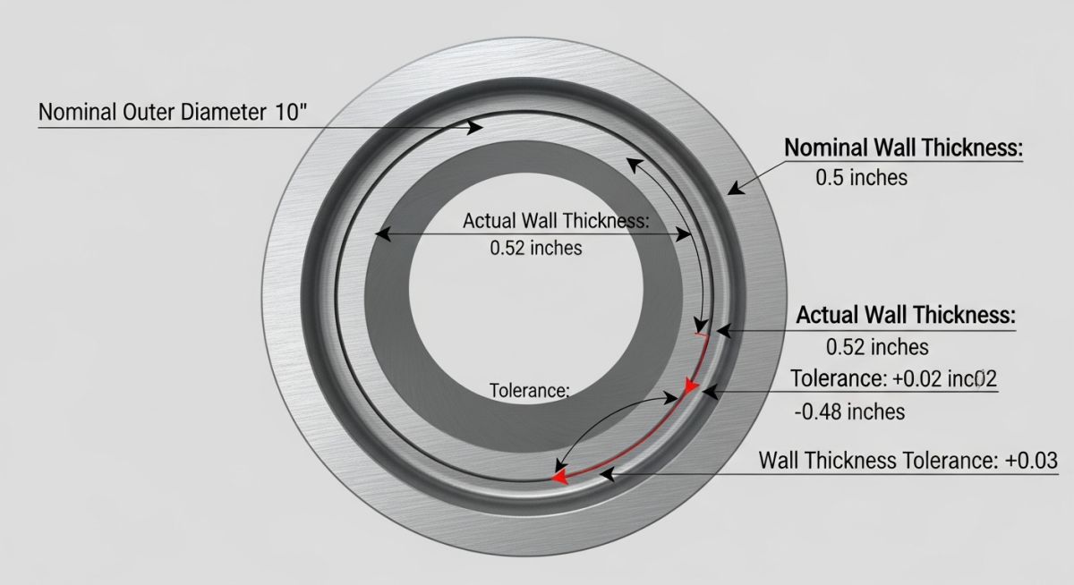
Learn what mill tolerance is, how it affects piping and steel manufacturing, and why it matters for engineering design.
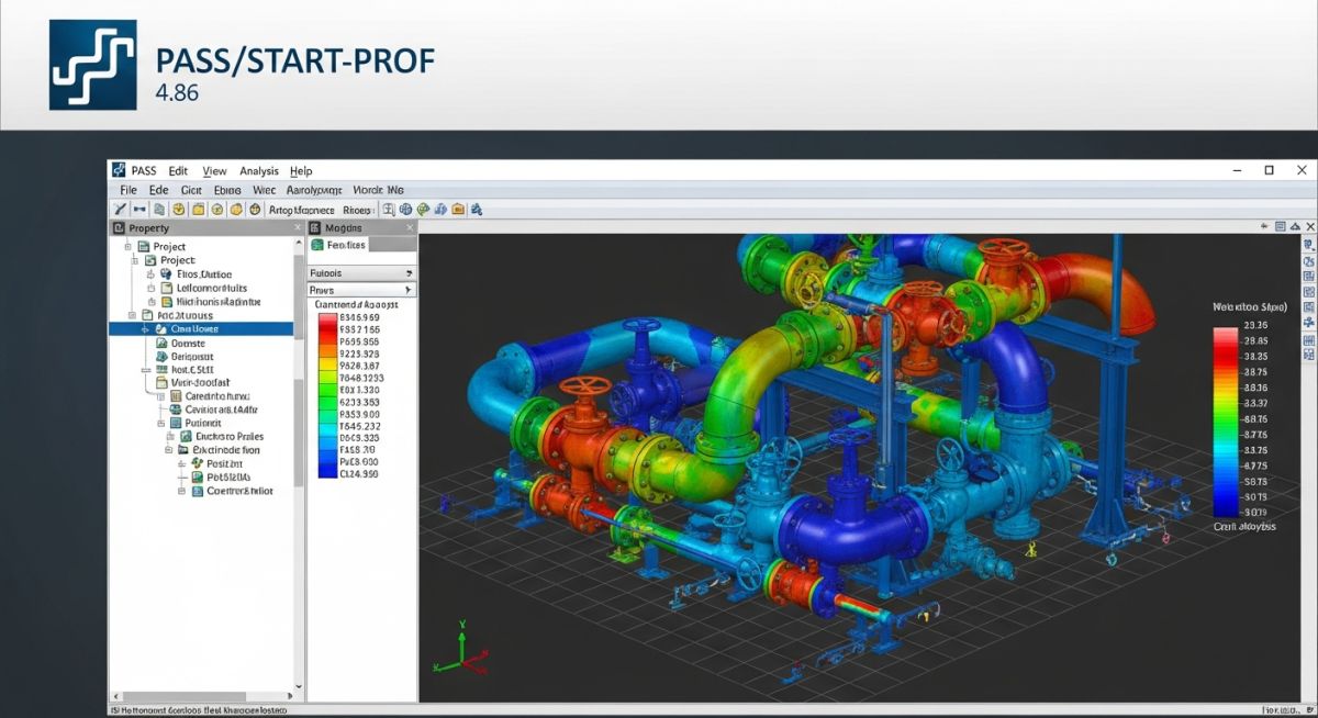
Discover the latest features and capabilities of PASS/START-PROF 4.86, the advanced pipe stress analysis software for modern piping engineers.
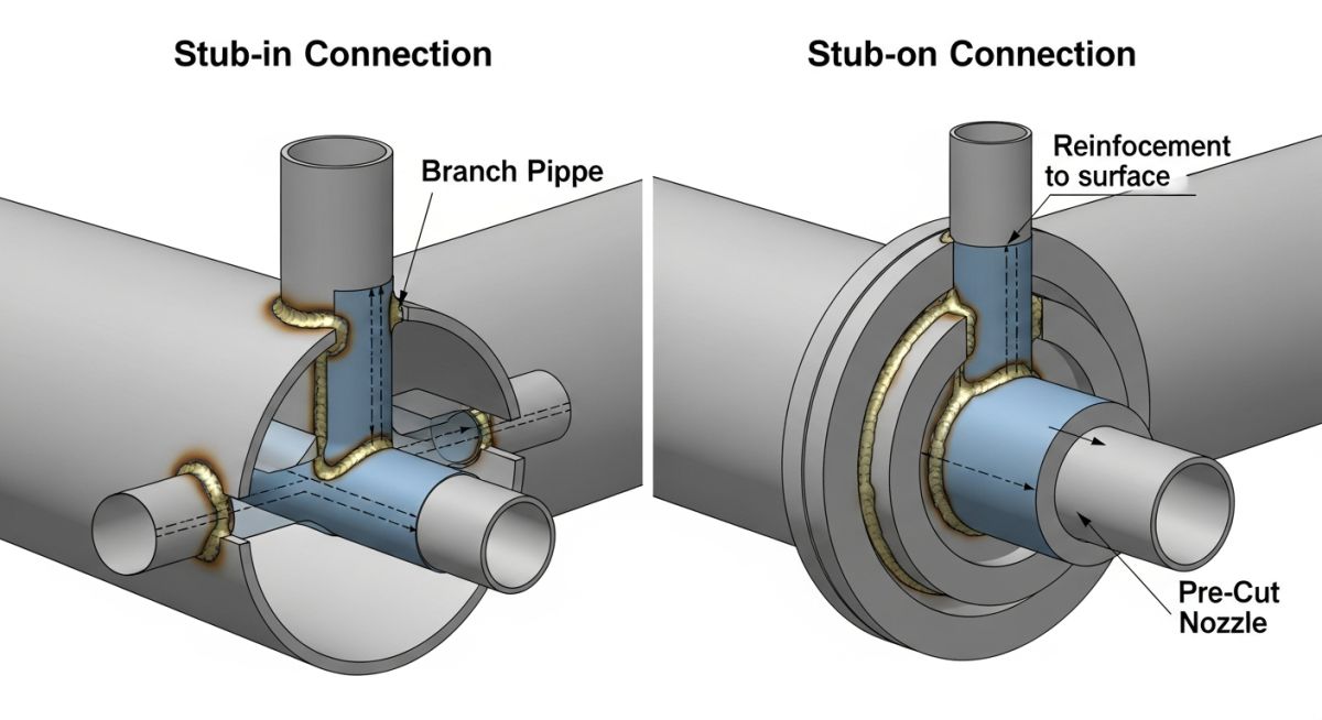
Learn the key differences between stub-in vs stub-on piping connections, including design, reinforcement, welding, and industry applications.
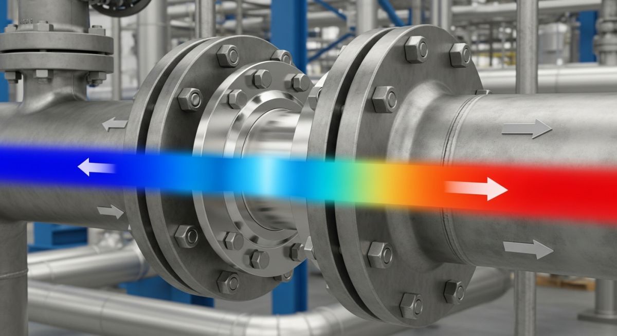
Learn what a restriction orifice (RO) is, how it works, its key types, industrial applications, and essential sizing guidelines.
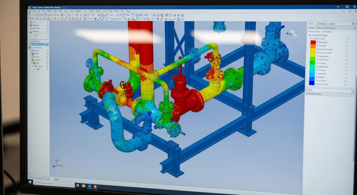
Learn the fundamentals of pipe stress analysis, its importance in piping design, key codes like ASME B31.3, and essential software tools.
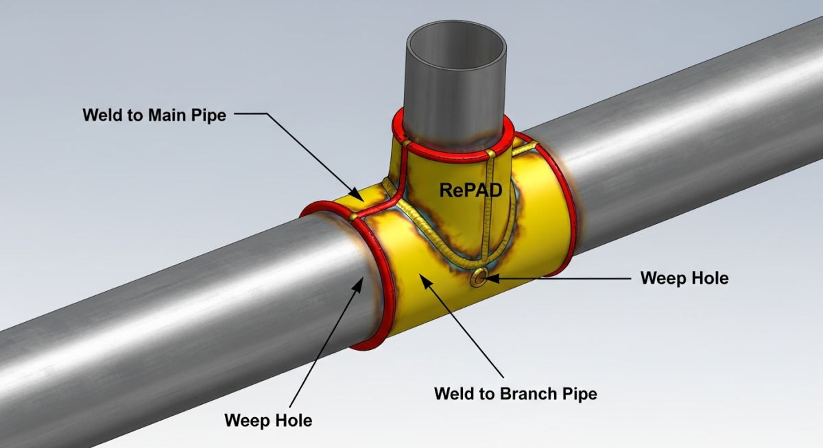
Learn what a reinforcement pad (RePAD/RF Pad) is, how it works, and its critical role in piping and pressure vessel design.