Methods for Submerged Pipeline Buoyancy Control and Marine Stability
In my 20 years of managing offshore pipeline installations, I have seen firsthand how unforgiving the marine environment can be. When you lay a pipeline across a riverbed, estuary, or deep-sea trench, you are fighting a constant battle against physics. A hollow steel pipe filled with gas or light hydrocarbons is naturally buoyant. Without proper engineering intervention, the upward force of displaced water will lift the pipeline off the seabed, exposing it to destructive hydrodynamic currents, debris impact, and catastrophic structural failure.
Controlling this buoyancy is not just about adding weight; it is about balancing geotechnical parameters, hydrodynamic drag, installation stresses, and long-term environmental changes. In this guide, I will share the exact engineering methods, calculations, and field-proven strategies we use to guarantee subsea pipeline stability in the most challenging marine environments.
- Understand the balance between vertical buoyancy forces and downward gravity vectors.
- Master the application of Concrete Weight Coatings (CWC) and mechanical anchoring systems.
- Learn to calculate the required negative buoyancy safety factor under varying fluid densities.
- Implement field-tested QA/QC protocols to prevent pipeline flotation during installation and operation.
How Submerged Pipeline Buoyancy Control Prevents Uplift
Subsea Pipeline Uplift Prevention: The systematic application of downward force vectors to counteract the upward buoyant force exerted by displaced water on a hollow pipeline. This design balance is governed by DNV-ST-F101 to prevent catastrophic lateral and vertical displacement.
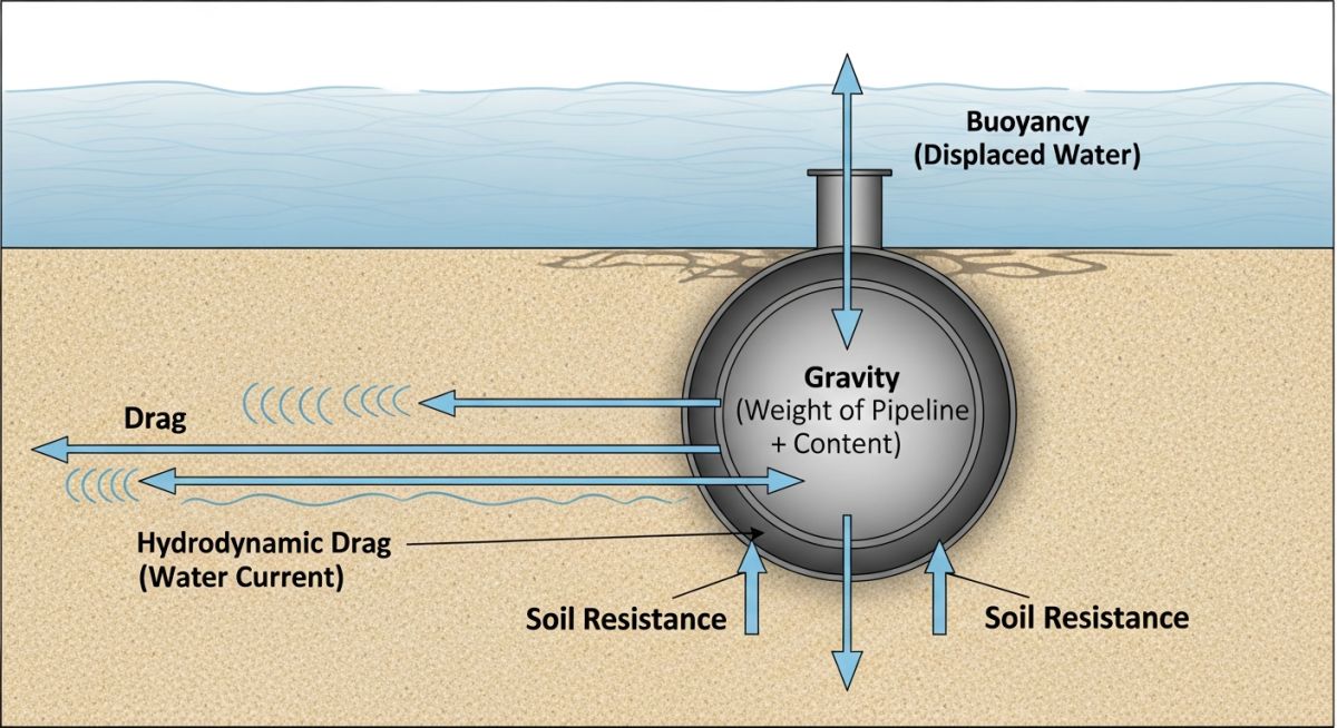
To design an effective stability system, we must first analyze the forces acting on the submerged asset. The primary upward force is buoyancy, which is directly proportional to the volume of water displaced by the outer diameter of the pipeline, including any coatings. The primary downward forces are the dry weight of the steel pipe, the weight of the internal corrosion-resistant alloy lining, the weight of the transported fluid, and the weight of any external coatings or soil backfill.
The Fundamental Buoyancy Equation
In my practice, we calculate the net buoyancy force per unit length using a fundamental balance of forces. The upward buoyant force is calculated as the density of the surrounding water multiplied by the gravitational acceleration multiplied by the total displaced volume of the pipeline per unit length.
To ensure the pipeline remains resting firmly on the seabed, the submerged weight of the pipeline must exceed this buoyant force by a specified safety margin. This relationship is expressed as the negative buoyancy safety factor, which is the total downward vertical force divided by the upward buoyant force. For stable operations, this factor typically ranges from 1.1 to 1.4, depending on the wave and current conditions of the project site.
Primary Methods for Buoyancy Control
There are four primary engineering methods used to achieve submerged pipeline buoyancy control in modern offshore projects:
- Concrete Weight Coating (CWC): This is the most common method for continuous negative buoyancy. A high-density concrete jacket, often reinforced with steel wire mesh, is applied over the anti-corrosion coating. This provides both continuous downward weight and mechanical protection against third-party impacts such as anchors and fishing gear.
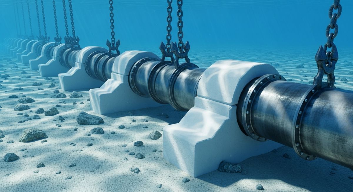
- Set-On Weights (Bolt-On Clamps): Individual concrete or cast-iron weights are bolted onto the pipeline at calculated intervals. This method is highly effective for river crossings or shallow water areas where continuous coating is not economically viable.
- Mechanical Anchor Systems: Helical screw anchors or soil anchors are driven into the seabed on either side of the pipeline, with a high-strength strap securing the pipe. This relies on the shear strength of the soil rather than pure gravity.
- Geotextile Mattresses and Rock Dumping: Placing flexible concrete block mattresses or dumping graded quarry rock over the pipeline. This provides both negative buoyancy and excellent protection against hydrodynamic scour.
Design Parameters for Subsea Pipeline Stability
Subsea Stability Parameters: The physical and environmental design limits required to calculate the minimum concrete coating thickness and anchor spacing for marine pipelines. These parameters are calibrated against wave and current velocities specified in DNV-RP-F109.
The table below outlines typical design parameters for concrete weight coatings across various nominal pipe sizes to achieve a target negative buoyancy safety factor of 1.2 in seawater with a density of 1025 kilograms per cubic meter.
| Nominal Pipe Size (inches) | Steel Wall Thickness (mm) | CWC Thickness (mm) | Concrete Density (kg/m³) | Submerged Weight Empty (kg/m) | Safety Factor (Empty) |
|---|---|---|---|---|---|
| 12 | 12.7 | 40 | 2400 | 45.2 | 1.25 |
| 18 | 15.9 | 50 | 2400 | 78.6 | 1.22 |
| 24 | 19.1 | 65 | 3040 | 142.1 | 1.28 |
| 36 | 25.4 | 80 | 3040 | 285.4 | 1.24 |
This matrix maps the core technical entities, structural acronyms, and physical parameters to their governing international standards.
| Entity / Acronym | Physical Parameter | Governing Standard | Engineering Application |
|---|---|---|---|
| CWC | Concrete Density & Thickness | ISO 21809-5 | Continuous negative buoyancy and external mechanical protection. |
| Lateral Stability | Hydrodynamic Drag & Lift Forces | DNV-RP-F109 | Ensuring the pipeline does not slide laterally under wave action. |
| Soil Resistance | Friction Coefficient & Shear Strength | API RP 1111 | Calculating the resistance of the seabed soil against pipe movement. |
| Cathodic Protection | Anode Weight & Spacing | NACE SP0169 | Preventing corrosion under the concrete weight coating. |
Field Verification for Submerged Pipeline Buoyancy Control
Buoyancy Control Field Verification: The mandatory quality assurance protocol executed on-site to verify concrete coating integrity, anchor torque, and trench depth before pipeline flooding and commissioning. These field checks ensure compliance with ASME B31.4 and DNV-ST-F101.
Before any subsea pipeline is lowered into the water, the field engineering team must verify that all buoyancy control measures have been executed to the exact design specifications. Failure to do so can result in immediate pipeline flotation or lateral buckling during the lay process.
-
Concrete Weight Coating Integrity: Inspect 100% of the CWC surface for cracks, spalling, or voids. Any crack wider than 2 millimeters must be repaired using approved marine epoxy compounds.
-
Anode Installation Check: Verify that sacrificial zinc anodes are securely welded to the steel pipe and that the electrical continuity straps are intact before the concrete coating is applied over the joint.
-
Anchor Torque Verification: For mechanical anchor systems, verify that every helical screw anchor achieves the minimum design installation torque specified in the geotechnical report.
-
Trench Depth Profile: Perform a high-resolution bathymetric survey to confirm that the trench depth meets the minimum cover requirements to prevent hydrodynamic lift.
-
As-Built Surveying: Document the exact coordinates and elevations of all set-on weights or geotextile mattresses using ROV-mounted cameras and sonar systems.
Field Case Study: Real-World Application
During a major natural gas pipeline project in a shallow water estuary, the engineering team faced extreme tidal currents reaching 3.5 meters per second. The seabed consisted of highly mobile, fine silty sand. Initial calculations showed that a standard 24-inch pipeline with standard anti-corrosion coating would experience severe lateral displacement and eventual flotation during spring tides due to soil liquefaction and hydrodynamic lift.
I recommended a dual-stabilization approach. First, we applied a 75-millimeter high-density concrete weight coating (3040 kg/m³) to the pipeline, which increased the negative buoyancy safety factor to 1.35 in the empty condition. Second, we specified the installation of mechanical helical screw anchors spaced at 12-meter intervals across the high-current zone. This system was successfully installed, and subsequent ROV inspections over a three-year period confirmed zero lateral or vertical movement of the pipeline, even after a Category 3 hurricane passed directly over the site.
This project proved that relying on a single method of buoyancy control is often insufficient in dynamic marine environments. Combining continuous weight coatings with mechanical anchoring provides the redundancy required to safeguard critical infrastructure.
Frequently Asked Engineering Questions
What is the minimum safety factor for pipeline buoyancy control?
How does soil liquefaction affect submerged pipeline stability?
Why is concrete weight coating preferred over continuous trenching?
Can concrete weight coating damage the pipeline’s anti-corrosion coating?
How do you calculate the spacing of set-on weights?
What role does water salinity play in buoyancy calculations?
Complete Course on
Piping Engineering
Check Now
Key Features
- 125+ Hours Content
- 500+ Recorded Lectures
- 20+ Years Exp.
- Lifetime Access
Coverage
- Codes & Standards
- Layouts & Design
- Material Eng.
- Stress Analysis
