Table of Contents
What is a Reinforcement Pad in Piping Design?
In my 20 years of piping design and field engineering, I have seen many piping failures. One of the most common culprits is a poorly designed or completely omitted reinforcement pad. When you cut a hole in a run pipe to branch off a new line, you severely compromise the structural integrity of that header. The internal pressure and external piping loads concentrate directly at that crotch weld.
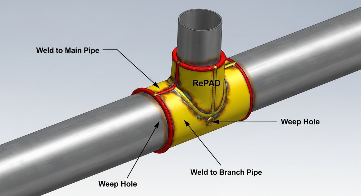
That is where the reinforcement pad—commonly known as a RePAD or RF Pad—comes into play. It acts as a structural doubler plate, restoring the metal area lost to the cutout. Throughout my career, I have guided junior engineers through the complex calculations of the area replacement method. Skipping this step or executing it poorly can lead to catastrophic localized failures during hydrotesting or, worse, during live plant operations.
Key Engineering Takeaways
- Restores the structural cross-sectional area lost when cutting a branch opening.
- Distributes localized bending moments and thermal expansion stresses.
- Must feature at least one threaded weep hole to vent gases and detect leaks.
- Requires strict compliance with the area replacement rules of ASME B31.3.
- Typically fabricated from the exact same material plate as the run pipe to prevent galvanic corrosion and thermal expansion mismatch.
How Does a Reinforcement Pad Restore Piping Integrity?
When a hole is cut into a header pipe, the stress distribution profile changes dramatically. The hoop stress, which is normally uniform across the pipe wall, must find a path around the opening. This creates a high stress concentration factor at the sides of the opening.
To counter this, we use the Area Replacement Method. The fundamental principle is simple: the cross-sectional area of the metal removed by the hole must be replaced by excess metal available in the run pipe wall, the branch pipe wall, the structural welds, and, if those are insufficient, an external reinforcement pad.
The Area Replacement Formula
According to ASME B31.3 Paragraph 304.3.3, the required reinforcement area Ar for a 90-degree branch connection is calculated as:
Where:
- d1 = The effective length of the opening in the corroded condition.
- th = The pressure design thickness of the header pipe.
The available area Aa is the sum of the excess thickness in the header (A1), the excess thickness in the branch (A2), and the area of the fillet welds (A3). If A1 + A2 + A3 is less than Ar, we must add a reinforcement pad to provide the remaining area (A4):
Where:
- Dp = Outside diameter of the reinforcement pad.
- d2 = Outside diameter of the branch pipe.
- Tp = Thickness of the reinforcement pad.
Never allow a welder to seal-weld or plug the weep hole (tell-tale hole) on a reinforcement pad. During the welding process, high temperatures cause air and moisture trapped between the pad and the pipe to expand. If there is no vent, this expanding gas will blow pinholes through your hot weld metal, causing severe porosity. In service, a plugged weep hole prevents you from detecting a pinhole leak in the primary nozzle weld, leading to hidden corrosion and sudden, catastrophic failure.
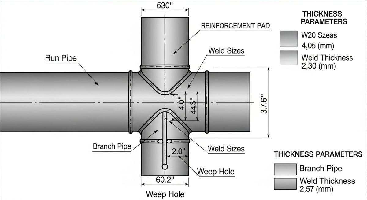
Standard Dimensions for a Reinforcement Pad
While custom calculations are always required for high-pressure systems, standard piping design practices utilize pre-calculated dimensional tables for low to medium-pressure utility lines. Below is a typical engineering reference table for standard carbon steel reinforcement pads.
| Branch Size (NPS) | Header Size (Min NPS) | Pad Outer Diameter (OD – mm) | Pad Thickness (mm) | Weep Hole Size (NPT) |
|---|---|---|---|---|
| 2″ | 4″ | 115 | 6.0 | 1/4″ |
| 3″ | 6″ | 165 | 8.0 | 1/4″ |
| 4″ | 8″ | 220 | 10.0 | 1/4″ |
| 6″ | 12″ | 320 | 12.0 | 1/4″ |
| 8″ | 16″ | 420 | 12.0 | 1/2″ |
| Entity / Acronym | Technical Definition | Physical Parameter / Value | Code Reference |
|---|---|---|---|
| RePAD / RF Pad | Reinforcement plate welded around a branch connection to restore pressure-containing capability. | Thickness typically matches run pipe thickness (Tp ≤ Trun). | ASME B31.3 Para 304.3.3 |
| Weep Hole | A threaded vent hole used to release welding gases and perform pneumatic leak testing. | Typically 1/4″ NPT or 1/2″ NPT; must not be permanently plugged. | ASME B31.3 Para 328.5.4 |
| Area Replacement | The mathematical method of replacing removed metal area with excess adjacent metal. | Aavailable ≥ Arequired | ASME B31.3 / ASME Sec VIII Div 1 |
How to Inspect a Reinforcement Pad on Site?
During my time as a lead field engineer, I developed a strict quality control protocol for inspecting reinforcement pads before they were cleared for hydrotesting. Welders often try to cut corners, especially on the back-welds and the weep hole placement. Use this checklist on your job site to ensure complete compliance.
Field Inspection Checklist
-
Material Verification (PMI): Ensure the reinforcement pad material matches the run pipe material specification (e.g., ASTM A106 Gr. B pipe must use ASTM A516 Gr. 70 or ASTM A106 plate/pipe for the pad).
-
Weep Hole Check: Verify that at least one weep hole (1/4″ or 1/2″ NPT) is drilled and tapped. Ensure it is positioned at the lowest point (for horizontal lines) to allow condensation drainage.
-
Pneumatic Leak Test: Perform a low-pressure air test (typically 15 psi / 1.0 bar) through the weep hole using soapy water on the welds to check for bubbles.
-
Weld Profile Inspection: Check that the outer fillet weld is continuous and matches the design leg length (typically equal to the pad thickness).
-
Curvature Fit-Up: Ensure the pad is pre-formed to match the exact outer curvature of the run pipe. The gap between the pad and the pipe must not exceed 1.5 mm before welding.
Why Did This Unreinforced Nozzle Fail in Service?
In 2018, I was called to a gas processing plant experiencing repeated shutdowns on a 16-inch hydrocarbon header operating at 450 psi and 220°C. A 6-inch unreinforced branch connection had developed a severe crack along the crotch weld. The original design team had assumed that because the header was Schedule 40, there was enough “excess thickness” to bypass a reinforcement pad. However, they completely ignored the high thermal expansion loads and mechanical vibrations from an upstream compressor.
We performed a Finite Element Analysis (FEA) which revealed that the localized stress at the crotch weld was 2.4 times the allowable limit under thermal cycling. We designed a custom split reinforcement pad (fabricated in two halves to wrap around the existing branch) with a thickness of 12 mm and a 1/4″ NPT weep hole. Once welded and pneumatically tested, the localized stress dropped by 58%, bringing the system fully into compliance with ASME B31.3. The line has been running leak-free for over eight years.
My recommendation from this event is clear: never rely solely on basic area replacement calculations for lines subject to high vibration or thermal cycling. Always perform a secondary stress analysis to determine if a reinforcement pad or a forged integrally reinforced fitting (like a Weldolet) is required to handle external piping loads.
Common Questions About a Reinforcement Pad
What is the primary purpose of a weep hole in a reinforcement pad?
Can we use a reinforcement pad on a piping system operating under cyclic service?
How do you perform a pneumatic test on a reinforcement pad?
What is the difference between a RePAD and a Weldolet?
Can the reinforcement pad material be different from the run pipe material?
What is the maximum thickness allowed for a reinforcement pad?
===FAQ_BLOCK===
Complete Course on
Piping Engineering
Check Now
Key Features
- 125+ Hours Content
- 500+ Recorded Lectures
- 20+ Years Exp.
- Lifetime Access
Coverage
- Codes & Standards
- Layouts & Design
- Material Eng.
- Stress Analysis

📚 Recommended Resources: reinforcement pad
Read these Guides
- 📄 Reinforcement Pad Calculations for Pipe Branch: Piping Course
- 📄 Understanding Elliptical RF Pad Calculations: Reinforcement Zone and External Pressure Considerations
- 📄 What is a Pipe Wear Pad? Functions, Sizing, and Code Differences
- 📄 Tank Pad Foundation: The 2026 Engineering Guide to API 650 Standards
🎓 Advanced Training


Related posts:
![An engineer performing an API 579 fitness for service assessment on an industrial pressure vessel.]()
How to Perform API 579 Fitness for Service Assessment
![3D CAD render of a bolted flange joint assembly showing a compressed gasket.]()
Understanding Gasket m and y Factors in Flange Design
![PASS/START-PROF 4.86 pipe stress analysis software interface displaying a 3D piping model.]()
PASS/START-PROF 4.86 Released: Discover the New Pipe Stress Analysis Capabilities
![ASME certification mark stamped on an industrial pressure vessel nameplate]()
What is ASME Certification? Procedure and Mark Explained
![Professional technician inserting a high-pressure hydro jetting nozzle into a sewer pipe cleanout.]()
What is Hydro Jetting and How Does It Work?
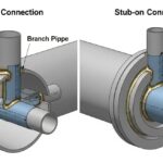
![Side-by-side comparison diagram of stub-in and stub-on piping branch connections.]()
Stub-in vs Stub-on Piping Connections: Engineering Design Guide