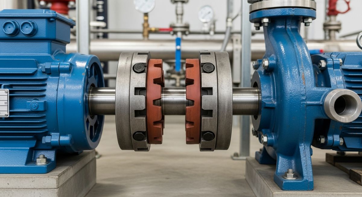
What is a Pump Coupling and How to Select It
In my 20 plus years of commissioning rotating equipment across petrochemical plants and water treatment facilities, I have seen minor components cause catastrophic plant shutdowns. Among these, the humble pump coupling is frequently misunderstood. Many junior engineers treat it as a simple piece of metal connecting two shafts. In reality, it is the mechanical “fuse” and the primary dampening system of your entire pumping assembly.
When a pump operates at 3600 RPM, even a microscopic misalignment can generate massive cyclic forces. These forces quickly destroy bearings, ruin expensive mechanical seals, and crack shafts. Selecting, installing, and maintaining the correct coupling is not just a minor design step; it is a fundamental requirement for achieving a high Mean Time Between Failures (MTBF) in your piping systems.
Key Engineering Takeaways
- Understand how couplings act as a protective barrier between the driver (motor) and the driven equipment (pump).
- Differentiate between rigid and flexible couplings based on misalignment tolerances and axial float.
- Learn the exact mathematical steps to calculate design torque and select service factors.
- Master the field verification steps required to prevent premature coupling failure during commissioning.
How a Pump Coupling Functions in Piping Systems
Torque Transmission Mechanics: The primary operational mechanism of a pump coupling involves transferring rotational energy from the driver to the impeller shaft while dampening shock loads and compensating for angular, parallel, and axial shaft misalignments under API 671 guidelines.
To select the correct coupling, we must first analyze the forces at play. A pump coupling must perform three primary functions simultaneously: transmit torque, accommodate shaft misalignment, and allow for axial end float.
1. Torque Transmission and Service Factors
The coupling must transmit the full rotational power of the motor to the pump shaft without slipping or shearing. To calculate the nominal torque (Tn) in Newton-meters, we use the following standard mechanical formula:
Where:
P = Driver power in kilowatts (kW)
n = Rotational speed in revolutions per minute (RPM)
However, designing for nominal torque alone is a recipe for field failure. We must apply a Service Factor (Sf) to account for startup inertia, fluid pulsations, and cyclic loading. The Design Torque (Td) is calculated as:
For a standard centrifugal pump driven by an electric motor, a service factor of 1.5 is typical. However, if you are driving a reciprocating positive displacement pump with a diesel engine, the service factor can jump to 2.5 or higher due to severe torque fluctuations.
2. Managing Shaft Misalignment
No matter how skilled your millwright is, perfect shaft alignment is impossible to maintain during operation. Thermal expansion of the pump casing, piping strain, and foundation settling will cause shafts to shift. Couplings must handle three types of misalignment:
- Parallel (Offset) Misalignment: The shaft centerlines are parallel but do not lie on the same axis.
- Angular Misalignment: The shafts meet at a slight angle, causing cyclic bending stresses.
- Axial Misalignment (End Float): The shafts move closer together or further apart, often caused by thermal growth of the pump shaft.
3. Spacer Couplings and API 610 Compliance
In process industries, particularly oil and gas refineries operating under API 610 standards, spacer couplings are mandatory. A spacer coupling features a removable center section (the spacer) between the two shaft hubs.
This design allows maintenance crews to replace the pump’s mechanical seal and bearings without removing the motor or disconnecting the pump casing from the process piping. This “back pull-out” capability reduces maintenance downtime from days to hours.
Selecting the Right Pump Coupling for Applications
Coupling Selection Criteria: The process of matching a specific coupling design to an industrial pump application based on torque capacity, speed limits, misalignment tolerances, and environmental conditions in accordance with ASME B106.1M.
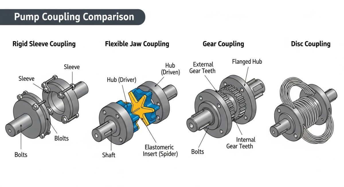
Choosing between a rigid and a flexible coupling is your first major decision. Rigid couplings are limited to applications where the shafts are perfectly aligned and cannot tolerate any relative movement. Flexible couplings, on the other hand, use elastomeric elements or metallic discs to allow for slight movements.
Rigid vs. Flexible Coupling Comparison
| Coupling Type | Sub-Type | Torque Capacity | Misalignment Tolerance | Lubrication Required | Typical Application |
|---|---|---|---|---|---|
| Rigid | Sleeve / Muff | Medium to High | Zero (0.0 mm) | No | Vertical turbine pumps, small line shafts |
| Rigid | Flanged | Very High | Zero (0.0 mm) | No | Heavy-duty vertical mixer shafts |
| Flexible (Metallic) | Metallic Disc | High | Low to Medium | No | API 610 process pumps, high-speed turbines |
| Flexible (Metallic) | Gear Coupling | Extremely High | Medium | Yes (Grease) | High-horsepower boiler feed pumps |
| Flexible (Elastomeric) | Jaw (Spider) | Low to Medium | High | No | Standard water pumps, fractional HP motors |
| Flexible (Elastomeric) | Tire Coupling | Medium | Very High | No | Slurry pumps, high-vibration applications |
Technical Mapping & Specifications Matrix
The following matrix maps the core technical entities, structural acronyms, and physical parameters to their governing international standards.
| Entity / Parameter | Acronym | Primary Standard Reference | Critical Design Limit |
|---|---|---|---|
| Distance Between Shaft Ends | DBSE | ASME B73.1 | Typically 3.5, 5.0, or 7.0 inches for process pumps |
| High-Performance Couplings | HP-Coupling | API 671 / ISO 10441 | Zero-backlash, continuous duty without lubrication |
| Torsional Vibration Analysis | TVA | API 610 Clause 6.9 | First torsional natural frequency must be 10% away from excitation frequencies |
| Maximum Allowable Misalignment | MAM | Manufacturer Specific | Angular: 1.0 degree; Parallel: 0.5 mm (typical flexible limits) |
Field Installation Checklist for Pump Couplings
Installation Quality Control: A systematic field verification protocol designed to ensure precise shaft alignment, correct gap settings, and proper bolt torque values during pump commissioning according to API RP 686.
During my years in the field, I have found that over 70% of premature coupling failures are caused by poor installation practices. To prevent this, I enforce a strict verification protocol before any rotating equipment is energized.
Pre-Commissioning Verification Steps
Field Case Study: Real-World Application
The Problem: Chronic Bearing Failures at a Chemical Plant
A major chemical processing plant was experiencing chronic bearing failures on a critical centrifugal pump transferring corrosive slurry. The pump bearings were failing every three months, and the mechanical seals were leaking consistently.
During my site inspection, I discovered that the maintenance team had replaced the original flexible disc spacer coupling with a rigid sleeve coupling to “save money and simplify maintenance.” This rigid connection was transferring all piping strain and thermal expansion directly from the pump casing to the motor bearings, causing severe shaft deflection.
The Solution & Outcome
I immediately ordered the removal of the rigid coupling and specified an API 610 compliant flexible metallic disc spacer coupling. We also performed a complete hot-alignment check to account for thermal growth when the pump reached its operating temperature of 120 degrees Celsius.
As a result, the pump’s vibration levels dropped from 8.5 mm/s to 1.2 mm/s. The bearing operating temperatures decreased by 18 degrees Celsius. Most importantly, the pump has now been running continuously for over 36 months without a single bearing or seal failure, saving the plant thousands of dollars in downtime and replacement parts.
My direct recommendation is simple: never compromise on coupling design to save on initial procurement costs. The long-term cost of bearing failures, seal leaks, and lost production will always outweigh the price of a high-quality, properly engineered flexible coupling.
Frequently Asked Engineering Questions
What is DBSE and why is it important for pump couplings?
Can a flexible coupling compensate for poor piping installation?
What are the primary differences between API 610 and API 671 couplings?
How do you identify and correct a soft foot condition?
Why do elastomeric couplings fail prematurely in high-temperature environments?
How does a spacer coupling facilitate pump maintenance?
===FAQ_BLOCK===
Complete Course on
Piping Engineering
Check Now
Key Features
- 125+ Hours Content
- 500+ Recorded Lectures
- 20+ Years Exp.
- Lifetime Access
Coverage
- Codes & Standards
- Layouts & Design
- Material Eng.
- Stress Analysis



