An Overview of Linear and Non-Linear Analysis in Piping Stress Calculations
Imagine designing a high-pressure steam line only to find that during the first thermal cycle, the pipe lifts off its support, transferring massive unexpected loads to a sensitive pump nozzle. In the linear world, we assume supports stay attached and friction doesn’t exist, but reality is messy. If your boundary conditions change state—whether it is a support gapping, a shoe sliding, or a hanger bottoming out—your static linear equations will fail you, leading to potential catastrophic fatigue or flange leakage.
This guide breaks down the transition from simple stiffness matrices to the iterative complexity of Piping Stress Non-Linear Analysis, ensuring your 2026 projects remain compliant and safe.
Key Engineering Takeaways
- Boundary Nonlinearity: Why gaps and friction require iterative solvers instead of simple matrix inversion.
- Convergence Logic: Understanding how the stiffness matrix [K] updates dynamically as supports engage or disengage.
- Standard Compliance: Applying non-linear results to meet ASME B31.3 and API 610 allowable load requirements.
What is Piping Stress Non-Linear Analysis?
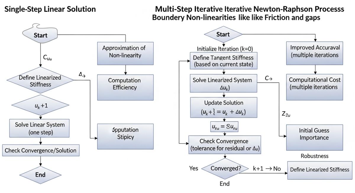
Piping Stress Non-Linear Analysis is an iterative calculation method used when system stiffness changes with displacement. Unlike linear analysis, it accounts for boundary condition changes such as support lift-off, friction resistance, and gaps. It solves the equation [K]{X} = {F} by recalculating the stiffness matrix [K] until convergence is achieved.
“In my 20 years of EPC execution, I have seen more field failures from ‘simple’ linear assumptions than from actual material defects. If you aren’t modeling friction coefficients and support gaps accurately, you aren’t doing stress analysis—you are doing guesswork.”
— Atul Singla, Founder of EPCLand
In This Technical Guide
Complete Course on
Piping Engineering
Check Now
Key Features
- 125+ Hours Content
- 500+ Recorded Lectures
- 20+ Years Exp.
- Lifetime Access
Coverage
- Codes & Standards
- Layouts & Design
- Material Eng.
- Stress Analysis
Technical Proficiency Check
Validate your knowledge on Piping Stress Non-Linear Analysis
Which mathematical condition necessitates a Non-Linear Analysis in piping software?
The Core Mechanics of Linear vs. Piping Stress Non-Linear Analysis
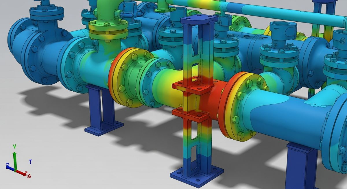
In the realm of structural mechanics, linear analysis operates on a principle of “proportionality.” The fundamental equation [K]{X} = {F} assumes that the stiffness matrix [K] remains constant regardless of the displacement {X}. This is a safe assumption for a pipe anchored at both ends with no external constraints. However, Piping Stress Non-Linear Analysis becomes mandatory the moment the system encounters boundary conditions that change state. For instance, when internal pressure and thermal expansion cause a pipe to lift off a support, the stiffness at that specific node drops to zero. A linear solver cannot “turn off” a support mid-calculation; it requires an iterative approach to redefine the matrix for every incremental change in load.
Beyond physical constraints, internal pressure plays a dual role. While pressure is typically treated as a linear load in simplified models, in Piping Stress Non-Linear Analysis, we must account for the “Bourdon Effect” and pressure stiffening. Large-diameter, thin-walled pipes under high pressure can exhibit significant changes in their structural stiffness. According to the ASME B31.3 Process Piping Standard, the interaction between pressure, weight, and thermal loads must be evaluated to ensure that non-linear boundary transitions (like friction or gaps) do not lead to localized overstressing at equipment nozzles.
Impact of Lift-up Supports in Piping Stress Non-Linear Analysis
Support lift-off (or “lift-up”) is perhaps the most common reason engineers switch to a non-linear solver. In a typical thermal cycle, a pipe might expand vertically. If the upward thermal force exceeds the sustained weight load at a support point, the pipe will physically separate from the steel structure. In a linear analysis, this support would continue to provide a “downward” pull (acting like a hanger), which is physically impossible for a simple resting support.
When performing Piping Stress Non-Linear Analysis, the software performs multiple passes. If it detects a negative (upward) reaction force at a resting support, it removes that constraint and restarts the calculation. This “load redistribution” is critical. The weight that was previously carried by the lifted support must now be carried by adjacent supports or, more dangerously, by the connected equipment such as pumps or turbines. Failing to model this accurately often results in underestimated nozzle loads and potential mechanical seal failures in rotating equipment.
Managing Support Gaps and Clearances in Piping Stress Non-Linear Analysis
In precision engineering, “gaps” or clearances are intentionally designed into lateral guides and limit stops to allow for small amounts of thermal expansion before a restraint engages. Handling these in Piping Stress Non-Linear Analysis requires a bi-linear stiffness approach. Initially, the pipe moves freely (stiffness = 0) within the gap. Once the displacement {X} equals the gap width, the stiffness of the steel structure is suddenly applied to the matrix. This “dead-band” behavior is a classic non-linear problem that can cause convergence oscillations if the gap is very small or if the system is highly sensitive to vibration.
According to ISO 14692 and other structural standards, the impact of these gaps is most pronounced in seismic or dynamic wind loading. If the gap is too large, the piping may develop excessive momentum before hitting the stop, leading to high impact loads. Conversely, if no gap is modeled, the analysis may over-predict the restraint forces, leading to over-designed (and expensive) support structures.
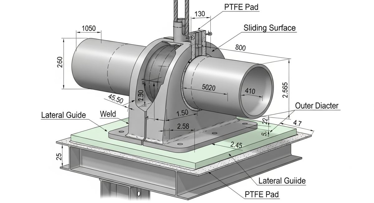
Factoring Support Friction in Piping Stress Non-Linear Analysis
Friction is the “invisible enemy” of the stress engineer. As a pipe expands horizontally, the friction force (F = μN) opposes the motion. This force is non-linear because it is dependent on the normal force (weight/pressure) and only acts until the pipe “breaks free” and starts sliding. In Piping Stress Non-Linear Analysis, the friction coefficient (μ) determines whether a pipe is “stuck” or “sliding” at any given iteration.
| Interface Material | Standard friction (μ) | Impact on Analysis |
|---|---|---|
| Steel on Steel | 0.30 | High lateral loads; requires robust guides. |
| Steel on Concrete | 0.45 | Maximum resistance; often causes support tipping. |
| PTFE (Teflon) on SS | 0.10 | Low resistance; ideal for equipment nozzles. |
| Lubricated Bronze | 0.15 | Moderate resistance; used in heavy manifolds. |
The challenge in 2026 for most EPC projects is the “Friction Sensitivity” check. Engineers must run the analysis twice: once with 0.0 friction (to check displacements) and once with 0.3+ friction (to check maximum nozzle loads). This ensures that the most conservative scenario is always accounted for in the Piping Stress Non-Linear Analysis workflow.
Friction Force & Nozzle Load Estimator
Estimate the lateral force generated by friction before a pipe “breaks free” and starts sliding. This is a critical input for Piping Stress Non-Linear Analysis.
Sum of Pipe weight + Fluid + Insulation at that node.
“The piping must overcome this force before any lateral thermal expansion can occur.”
EPCLand YouTube Channel
2,500+ Videos • Daily Updates
Real-World Application: Solving Convergence Issues in Complex Systems
The “Oscillating Support” Dilemma in a 24″ Steam Header
During a 2026 refinery expansion project, a 24-inch high-pressure steam header exhibited severe convergence failures in the stress model. Every time the solver ran, it entered an infinite loop: the weight caused a support to engage, but the resulting thermal expansion caused it to lift off. This “chatter” is a classic failure mode in Piping Stress Non-Linear Analysis where the system cannot find a stable equilibrium between the [K] matrix states.
The Problem
The gap at Support S-104 was set to 0.5mm. Friction (μ=0.3) was preventing the pipe from sliding laterally, which in turn forced a vertical “bowing” effect that caused the support to lift. This altered the weight distribution, causing the pipe to drop back down, repeating the cycle.
The Non-Linear Solution
We applied a Newton-Raphson iteration tweak by increasing the friction “stiffness” slope and widening the lateral gap to 2.0mm. This allowed the system to “find” its sliding state before the vertical lift-off threshold was met, achieving convergence in 14 iterations.
Technical Verdict: “In complex non-linear runs, mathematical convergence often requires engineering common sense. Adjusting gaps by just 1mm can be the difference between a failed run and a Rankine-compliant design.”
Expert Verdict on Software Selection for Advanced Calculations
Not all solvers are created equal. When selecting tools for Piping Stress Non-Linear Analysis, the robustness of the convergence algorithm is paramount. Software like CAESAR II, AutoPIPE, and ROHR2 utilize different iterative strategies—some handle friction as a force, while others handle it as a non-linear spring. For 2026 standards, ensure your software choice supports large-deflection analysis if your piping is flexible (like FRP or thin-wall stainless), as standard small-displacement non-linear theory may under-predict secondary stresses.
Don’t miss this video related to Piping Stress

Summary: Piping Stress Engineer is a Piping professional who provides technical expertise in piping design. In this article, let’s explore the ……
Expert Insights: Lessons from 20 years in the field
The Weight Convergence Trap: Always verify that your “Sustained” load case (Weight + Pressure) converges before attempting the “Expansion” case. If the non-linear boundary conditions don’t stabilize under gravity, they never will under thermal strain.
Friction is Directional: In complex loops, friction can act in multiple vectors. Ensure your Piping Stress Non-Linear Analysis software accounts for “Friction Stiffness” to avoid artificial stress spikes at the moment of sliding.
Gap Sensitivity: For high-energy piping, a 1/16″ (1.5mm) gap is standard. Modeling zero-gap lateral guides in a non-linear run often leads to over-conservative support designs and unnecessary costs.