What is Pressure Drop? Piping Pressure Drop Calculation and Equations
Imagine you have just commissioned a multi-million dollar cooling loop, only to find that the process fluid is barely reaching the heat exchangers at the end of the line. The pump is running at 100% capacity, yet the delivery pressure is negligible. This isn’t just a flow issue; it is a failure in Piping Pressure Drop Calculation. Misjudging pipe roughness or ignoring a few 90-degree elbows can lead to undersized pumps, wasted energy, and system-wide cavitation.
In this guide, we break down the physics of energy loss, from the foundational Darcy-Weisbach equation to real-world K-factor applications, ensuring your hydraulic designs are both efficient and reliable.
Key Takeaways
- Friction is the Primary Thief: Internal pipe roughness and fluid viscosity account for the majority of energy loss in steady-state flow.
- Darcy-Weisbach is King: While Hazen-Williams is convenient for water, the Darcy-Weisbach equation remains the most accurate tool for Piping Pressure Drop Calculation across all fluid types.
- Minor Losses Add Up: Valves and fittings (minor losses) can often exceed the friction loss of the pipe itself in complex plant layouts.
What is Piping Pressure Drop?
Piping pressure drop is the reduction in fluid pressure as it moves through a piping system, caused by internal friction between the fluid and pipe walls, and turbulence at fittings. Engineers use Piping Pressure Drop Calculation methods like the Darcy-Weisbach equation to determine the required pump head and ensure optimal flow rates.
“In my 20 years of industrial design, I’ve seen more energy wasted through ‘conservative’ pipe sizing than almost any other area. A precise Piping Pressure Drop Calculation doesn’t just save on pipe costs; it slashes the operational expenditure of the pumps for the entire life of the plant.”
— Atul Singla
Complete Course on
Piping Engineering
Check Now
Key Features
- 125+ Hours Content
- 500+ Recorded Lectures
- 20+ Years Exp.
- Lifetime Access
Coverage
- Codes & Standards
- Layouts & Design
- Material Eng.
- Stress Analysis
Engineering Check: Piping Pressure Drop Calculation
Test your knowledge on fluid friction and head loss
Which equation is considered the most universally accurate for Piping Pressure Drop Calculation involving any Newtonian fluid?
Why is Piping Pressure Drop Calculation critical for System Design?
In the world of hydraulic engineering, energy is never truly "lost"—it is simply converted into heat through friction and turbulence. A precise Piping Pressure Drop Calculation serves as the backbone for selecting the correct pump or compressor. If the calculation is too conservative, you end up with oversized equipment that operates far from its Best Efficiency Point (BEP), leading to increased vibration and premature seal failure. Conversely, underestimating the drop results in insufficient flow, stalling production lines.
Beyond hardware selection, understanding pressure drop is vital for safety and process integrity. For instance, in volatile fluid transport, an excessive pressure drop could lower the local pressure below the fluid's vapor pressure, triggering cavitation. High-quality data on friction losses allows engineers to maintain the required Net Positive Suction Head (NPSH) for downstream equipment, ensuring long-term reliability.
Defining Pressure Head in Piping Pressure Drop Calculation
Engineers often express pressure in terms of "Head" (meters or feet) rather than strictly PSI or Bar. Head represents the height of a liquid column that the fluid's energy could support. In a Piping Pressure Drop Calculation, we distinguish between Static Head (elevation change) and Dynamic Head (friction and velocity).
Engineering Tip: Always convert your pressure units to a consistent head basis when working with pumps. The Hydraulic Institute provides extensive standards on how head affects pump performance curves.
Factors Affecting Piping Pressure Drop Calculation
Calculating the total energy loss requires a deep dive into the physical environment of the pipe. The primary variables include:
Fluid Properties & Viscosity
Viscosity is the fluid's internal resistance to flow. High-viscosity fluids, like crude oil or syrups, generate significant internal shear, leading to massive friction losses. In any Piping Pressure Drop Calculation, the fluid's density and kinematic viscosity are the first inputs required to determine the Reynolds Number.
Mechanical Pipe Roughness
No pipe is perfectly smooth. Whether it is Carbon Steel, PVC, or Stainless Steel, the internal surface has microscopic peaks and valleys (absolute roughness, ε). Over time, corrosion and scaling increase this roughness, which is why a 2026 design must account for the "aged" condition of the pipe to ensure the Piping Pressure Drop Calculation remains valid over the plant's lifespan.
Changes in Elevation
Gravity is a constant player. When a fluid moves uphill, it loses pressure energy to gain potential energy. While this is technically a "reversible" change (unlike friction), it must be factored into the Piping Pressure Drop Calculation to determine the total discharge pressure required at the source.
Major Piping Pressure Drop Calculation Equations
Selecting the right mathematical model is critical for accuracy. While various empirical formulas exist, industrial piping design typically relies on three primary equations depending on the fluid type and application.
Darcy-Weisbach Equation (The Industry Standard)
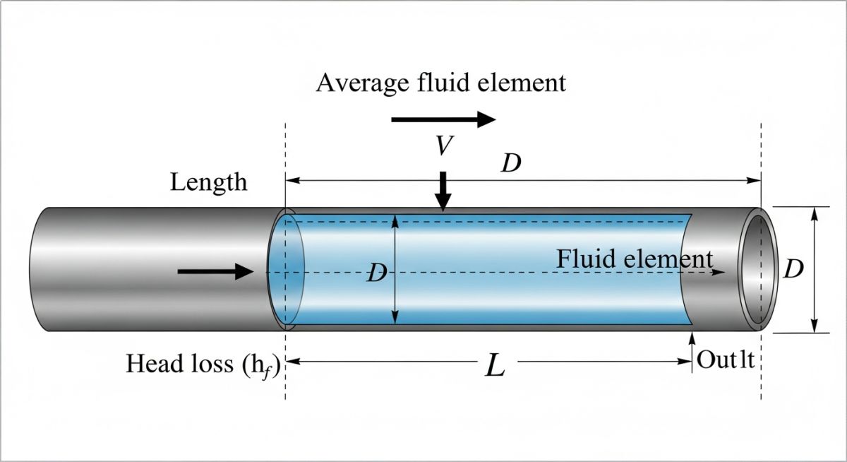
The Darcy-Weisbach equation is the most robust method for Piping Pressure Drop Calculation. It is valid for all flow regimes (laminar and turbulent) and any Newtonian fluid. The formula is expressed as:
hf = f × (L/D) × (v2 / 2g)
Here, f is the Darcy friction factor, often determined using the ASME recognized Moody Diagram or the Colebrook-White equation.
Hazen-Williams Equation (Water Systems)
Commonly used in fire protection and municipal water distribution, this equation simplifies the Piping Pressure Drop Calculation by using a roughness coefficient (C). However, it is limited to water at ambient temperatures and does not account for viscosity changes.
Determining Flow Regimes for Piping Pressure Drop Calculation
Before calculating friction, you must identify if the flow is Laminar, Transitional, or Turbulent using the Reynolds Number (Re). This dimensionless value determines how the fluid interacts with the pipe walls.
| Flow Regime | Reynolds Number (Re) | Friction Characteristics |
|---|---|---|
| Laminar | < 2,300 | Smooth, streamlined flow; friction is independent of pipe roughness. |
| Transitional | 2,300 - 4,000 | Unstable flow; difficult to predict Piping Pressure Drop Calculation accurately. |
| Turbulent | > 4,000 | Eddies and swirls dominate; roughness significantly impacts pressure drop. |
Accounting for Fittings in Piping Pressure Drop Calculation
Fittings like elbows, tees, and valves introduce "minor losses" due to flow separation and secondary currents. In a compact process skid, these losses can actually outweigh the straight-pipe friction.
The Equivalent Length Method vs. K-Factors
Engineers typically use one of two methods for Piping Pressure Drop Calculation at fittings:
- Equivalent Length (Le): Treats each fitting as a specific length of straight pipe.
- K-Factor Method: Uses a resistance coefficient multiplied by the velocity head (K × v2/2g). This method is widely supported by American Petroleum Institute (API) standards for more precise modeling.
Quick Piping Pressure Drop Calculator (Darcy-Weisbach)
Estimate head loss based on flow velocity and pipe characteristics.
Based on g = 9.81 m/s2. Ensure all units are consistent for Piping Pressure Drop Calculation.
Optimizing a Petrochemical Transfer Line
The Challenge
A facility in Houston reported that a newly installed 300m hydrocarbon transfer line was failing to meet the required flow rate of 150 m3/h. Initial Piping Pressure Drop Calculation during the FEED stage had estimated a 2.5 bar drop, but field measurements showed a staggering 4.2 bar loss.
The bottleneck was causing the transfer pump to operate at the end of its curve, risking vibration damage.
The Engineering Audit
Upon auditing the as-built isometric drawings, two critical errors were identified:
- The original Piping Pressure Drop Calculation used "new pipe" roughness instead of "design life" roughness.
- Six additional high-performance globe valves were added during construction, each with a high K-factor that was never accounted for.
The Solution & Result
By recalculating the hydraulics using the K-factor method for all fittings and replacing three high-resistance elbows with long-radius bends, the total pressure drop was reduced by 1.8 bar. This brought the system back within the pump's operating window, saving an estimated $14,000 annually in electricity costs.
EPCLand YouTube Channel
2,500+ Videos • Daily Updates
Don't miss this video related to Piping Pressure Drop Calculation

Summary: Master Piping Engineering with our complete 125+ hour Certification Course: ......
Expert Insights: Lessons from 20 years in the field
-
1
Beware of "Rule of Thumb" Sizing: Relying on standard velocity limits (e.g., 2 m/s for liquids) without a formal Piping Pressure Drop Calculation often leads to oversized piping in short runs and undersized piping in long runs. Always verify with the Darcy-Weisbach equation.
-
2
Temperature Sensitivity: Viscosity is highly sensitive to temperature. A 10°C drop in heavy oil temperature can triple the friction factor, completely invalidating a Piping Pressure Drop Calculation performed at ambient conditions.
-
3
Valve Trim Matters: Not all valves are equal. A fully open gate valve has a negligible K-factor (approx. 0.1), while a globe valve can be as high as 10.0. Accurate Piping Pressure Drop Calculation requires specific manufacturer Cv data whenever possible.
-
4
Accounting for Aging: Always use an "aged pipe" roughness factor (usually 1.5x to 2x of new pipe) to ensure your system performance doesn't degrade below operational requirements within 5 years.
References & Standards
The methodology for Piping Pressure Drop Calculation is governed by several international engineering bodies. For verified data and standardized coefficients, consult the following:
- Refer to the ASME B31.3 Process Piping Standard for design pressure and safety factor considerations.
- Consult API RP 14E for recommended practices in sizing piping systems and erosional velocity limits.
- Use the ISO 12241 standard for thermal and hydraulic performance calculations in industrial installations.
- For friction factor accuracy, verify your coefficients against the Colebrook-White Formula.
Piping Pressure Drop Calculation: Frequently Asked Questions
How do you accurately perform a Piping Pressure Drop Calculation for viscous fluids?
Why is the Darcy-Weisbach equation preferred over Hazen-Williams?
What is the impact of pipe aging on pressure drop?
Can a high pressure drop cause pump cavitation?
Is the K-factor method better than the Equivalent Length method?
What are the best tools for 2026 industrial hydraulic modeling?
📚 Recommended Resources: Piping Pressure Drop Calculation
Read these Guides
- 📄 ASTM A312 vs ASTM A358 (2026): The Critical Manufacturing, NDT & Pressure Difference
- 📄 Piping Manifold Design Guide: Standards, Types & Engineering 2026
- 📄 Ultimate Guide to Steam Piping Design: Engineering Considerations for 2026
- 📄 Heat Exchanger Fouling Factor: Significance, Calculation & 2026 Standards
🎓 Advanced Training


Related posts:
![High-grade industrial Wing Nut Types and Applications for mechanical assemblies.]()
Wing Nut Types and Applications: The 2026 Engineering Guide
![Industrial Monorail Crane Systems installed in a modern manufacturing plant 2026.]()
Monorail Crane Systems: Design, Types & 2026 Standards Guide
![Lead engineer performing a Factory Acceptance Test FAT on an industrial skid system 2026]()
Factory Acceptance Test FAT: The 2026 Engineering Guide to Zero-Defect Delivery
![Professional engineering workspace showing a Basis of Design document layout for a 2026 project.]()
Basis of Design: How to Write a BOD for Engineering Projects in 2026
![Industrial Flare Knockout Drum Sizing and installation in a refinery relief system.]()
Flare Knockout Drum Sizing: Design & API 521 Standards (2026 Guide)
![Advanced Reboiler Control Systems in a modern petrochemical refinery 2026.]()
Reboiler Control Systems: Engineering Guide to Precision Control 2026


