The Ultimate Piping Isometric Drawing Checklist for 2026
In modern industrial construction, a robust Piping Isometric Drawing Checklist is the primary defense against costly field rework and procurement errors. By standardizing the Piping isometric checking procedure, engineering firms can ensure that 3D model data translates accurately into 2D deliverables, maintaining compliance with global piping codes and project specifications.
Definition: A piping isometric drawing checklist is a systematic verification document used by piping engineers to validate dimensions, orientation, material specifications, and symbols on an isometric drawing before it is released for fabrication (IFC).
Quick Navigation
Engineering Knowledge Check
1. Which ASME code primarily governs isometric requirements for process piping?
Complete Course on
Piping Engineering
Check Now
Key Features
- 125+ Hours Content
- 500+ Recorded Lectures
- 20+ Years Exp.
- Lifetime Access
Coverage
- Codes & Standards
- Layouts & Design
- Material Eng.
- Stress Analysis
Engineering Theory and Regulatory Standards
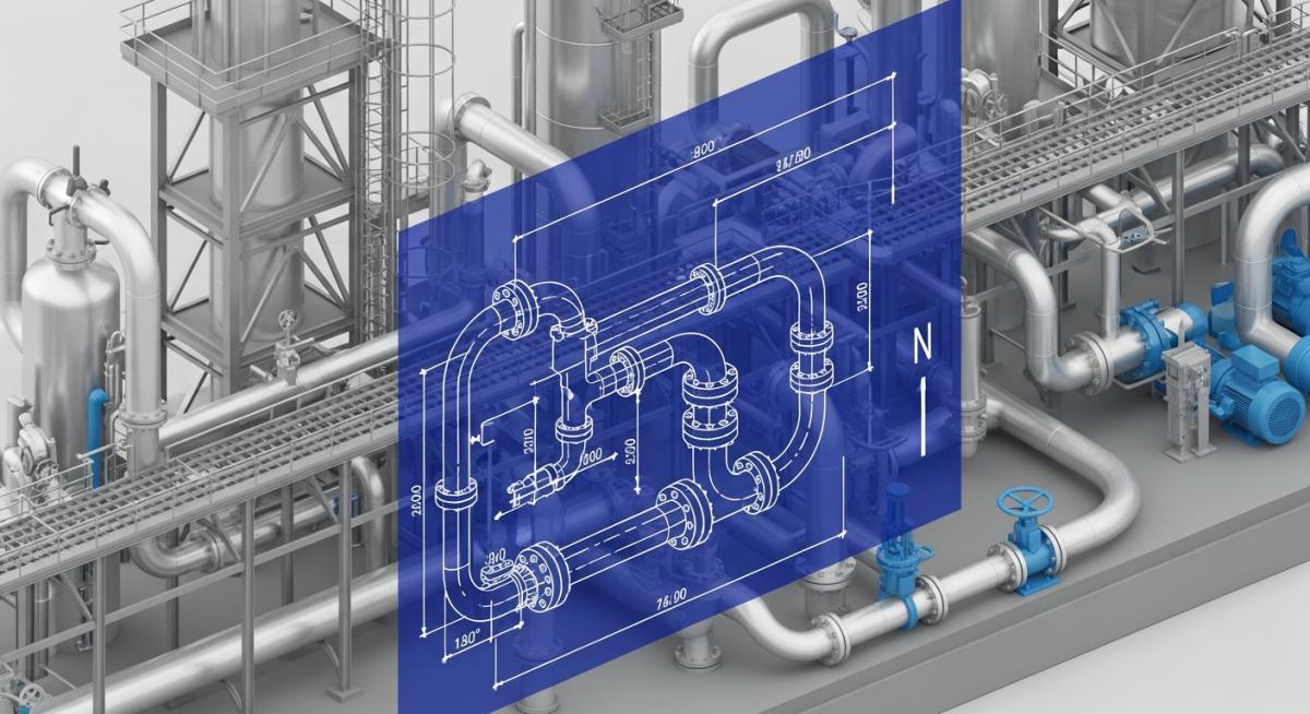
A Piping Isometric Drawing Checklist is not merely a drafting tool; it is a compliance mandate. Under ASME B31.3 isometric requirements, every drawing must provide enough detail to ensure the mechanical integrity of the piping system. Unlike orthographic projections, isometrics offer a 3D representation in a 2D plane, typically at a 30-degree angle, allowing for a comprehensive view of the routing, connectivity, and supports.

Figure 1: Standard layout for 2026 piping isometrics including symbols and BOM placement.
In 2026, the industry has shifted toward automated Isogen drawing quality control. However, manual verification remains essential for identifying “soft errors”—logical inconsistencies that software might overlook. One critical check is checking slope in piping isometrics. If a 1/100 slope is required for a condensate line but is missing from the isometric, the resultant “pocket” could lead to catastrophic water hammer.
Engineering Math: Calculating Slope (S)
To verify the vertical drop required over a horizontal run:
Vertical Drop (H) = Length (L) x Slope Percentage (%)
Example: For a 12m pipe with a 1.5% slope requirement:
H = 12,000mm x 0.015 = 180mm
Core Piping Isometric Drawing Checklist Items
The following table summarizes the mandatory verification points during a Piping isometric checking procedure. These points ensure that the Piping bill of materials verification aligns with the physical routing.
| Category | Checkpoint Description | Target Standard |
|---|---|---|
| Orientation | North Arrow direction check vs. Plant Layout | Project Spec 01-A |
| Symbology | Validation of Piping isometric symbols and abbreviations | ISA S5.1 / Project Legend |
| Bill of Materials | Detailed Piping bill of materials verification (Quantity/Rating) | ASME B31.3 / ASTM |
| Continuity | Check “Continued on Dwg…” references for line breaks | Process Flow Consistency |
| Sloping | Verification of gravity flow direction and pitch angle | Drainage Standards 2026 |
Every Piping Isometric Drawing Checklist must prioritize the connection points. Check that flange ratings match the mating equipment (e.g., pumps or vessels) and ensure that field welds are strategically placed to allow for transport and lifting limits.
The Professional Piping Isometric Checking Procedure
In 2026, while 3D modeling software streamlines the extraction process, it is mandatory for Senior Piping Checkers to perform a thorough manual review. Releasing drawings to the construction team without a verified Piping Isometric Drawing Checklist leads to site delays that no schedule can absorb. Quality assurance is not just about software accuracy; it is about the “back check” process.
The Standard Color-Code Procedure
To maintain 2026 engineering quality standards, checking must be performed on a hard print or a high-fidelity digital markup tool using the following color logic:
- GREEN: Correct/Verified
- RED: Error/Correction
- BLUE: Information/Comments
Fundamental Piping Isometric Checklist Points
A piping isometric checker must ensure the absolute correctness of the following 21 primary checkpoints to satisfy ASME B31.3 isometric requirements and project-specific Isogen drawing quality control.
- 01. Line numbers (Line ID)
- 02. Line specifications (Pipe Class)
- 03. Start & Endpoint locations
- 04. Branch connection details
- 05. Reducer types & orientations
- 06. Piping spec break (at valves/flanges)
- 07. Valve accessibility & orientation
- 08. Pipe support locations & types
- 09. Insulation limits & thickness
- 10. Instrument connection tapping
- 11. Flow arrows (Direction of flow)
- 12. High point vents / Low point drains
- 13. Hydro test vent/drain requirement
- 14. Equipment nozzle connectivity
- 15. Nozzle & Equipment numbers
- 16. 3D Coordinates (N, E, EL)
- 17. North Arrow orientation
- 18. Accurate Bill of Materials (BOM)
- 19. Valve Handwheel tag numbers
- 20. Continuation sheet references
Note: Every Piping bill of materials verification must ensure that each unique isometric sheet contains only one specification unless a spec break is clearly indicated as per the P&ID.
Pre-Check Checklist: Documents Required for Isometric Verification
Before initiating the Piping isometric checking procedure, the engineer must compile a comprehensive technical data package. Verification cannot occur in a vacuum; cross-referencing with these 2026 standard documents ensures that the Piping Isometric Drawing Checklist covers all inter-disciplinary requirements.
Primary Engineering Schematics
- P&ID: Source for line size, insulation, fluid commodity, and “No Pocket” or “Spectacle Blind” requirements.
- Piping Layouts & Sections: Used to verify the physical route, coordinates, elevations, and valve orientations.
Mechanical & Vendor Data
- Equipment Drawings: Essential for checking tie-in points at nozzles and confirming base elevations.
- Nozzle Orientations: Critical for confirming the angular position of connections vs. the plant north.
- Special Item Drawings: Dimensional data for non-standard components (strainers, flame arrestors).
Specifications & Standards
- Piping Material Specification (PMS): To identify special handling (e.g., no welding on PE-lined or galvanized pipes).
- Piping Support Standards: To validate that the support types shown on the ISO match approved project designs.
Stress & I&C Interface
- Stress Analysis Report: To ensure all mandatory “Stress Comments” (anchors, guides, spring settings) are updated.
- Instrument Hook-up Details: To verify end-connection types for proper instrument mounting and accessibility.
Advanced Verification Points for the Piping Isometric Drawing Checklist
Beyond the standard dimension and Bill of Material checks, a senior piping designer or engineer must verify critical operational and maintenance-related items. These checks, often missed during automated Isogen drawing quality control, prevent major operational issues down the line.
Operational Fluid Dynamics & Equipment Interfaces
- The pump suction is bigger than the discharge line (Refer to P&ID).
- The eccentric reducer (flat side top) used for the pump suction line is used for avoiding the air block in pump suction.
- The pump suction line and compressor suction line keep always a downward position, avoiding loops in the pump suction line to prevent cavitation risks.
- PSV outlet is always in a rising position (prevents liquid pooling).
- Drip legs are required for all steam line headers, with correct sizing verified by standard drawings. Shoe required for insulated lines (steam, chilled water, brine, steam condensate).
- Nozzle orientations should be kept as per the piping requirement and verified against vendor drawings.
- The straight length requirement for suction & discharge piping for compressors and certain pumps is as required by Vendor/project specs to ensure proper flow dynamics.
- The line configuration for lines containing magnetic flowmeters or vortex type flowmeters is such that they are always flooded.
- The orifice tapping orientation is done considering liquid or gas flow as applicable.
Accessibility and Fabrication Logistics
- Check the valve accessibility for maintenance purposes. The valve operating height must be min 250 mm to 1200 mm from floor level.
- Control station operating height 500 mm to 750 mm from floor level, located near walls or columns with supports on both sides of control valves.
- Lift check valve always horizontally using. Swing check valve vertically and horizontally using.
- Headroom clearance minimum 2.2m from ground/floor level. Avoid obstacles; keep piping routing neat and clear.
- Adequate pipe spool lengths are provided for wafer type butterfly and check valves to prevent the interference of the valve disc with adjacent piping items.
- The orientation of valve handwheel/lever is checked in the 3D model for proper access.
- There is adequate clearance between pipe support and the adjacent piping component (e.g. flange, drain valve) to allow for flange bolt removal and valve operation.
Fabrication Standards & Project Specs
- The minimum distance between welds is 50mm or five times the wall thickness whichever is greater.
- Unions are provided in galvanized piping where threaded in-line items need removal. Also, unions are provided at regular intervals (e.g. 24m) in straight pipe runs.
- Use weld neck flange for pressure piping as per ASME B31.3 isometric requirements.
- Appropriate break-up flanges are provided in piping with internal lining and hot-dipped galvanized piping.
- Lifting lugs are provided for removable spools wherever required as per project requirements.
EPCLand YouTube Channel
2,500+ Videos • Daily Updates
Case Study: Piping Isometric Drawing Checklist Failure Analysis
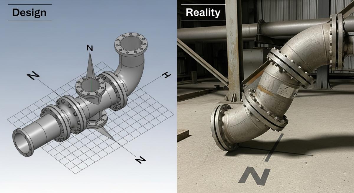
Visual Analysis: Contrast between 3D model orientation and field fabrication error.
Problem & Root Cause Analysis
During the 2026 brownfield expansion of a major refinery, a series of 14-inch stainless steel spools were fabricated and sent to the site. Upon arrival, construction crews discovered that the piping headers were oriented 90 degrees away from the tie-in points. Investigation revealed that the Piping isometric checking procedure had bypassed the “Global North vs. Plant North” verification step. This lack of a rigorous Piping Isometric Drawing Checklist allowed the automated Isogen output to default to an incorrect coordinate system.
The Solution & ROI Data
To mitigate the 15% field rework rate, the engineering team implemented a mandatory “Coordination Review” session. This session focused on Checking slope in piping isometrics and orientation verification against the master plot plan.
Impact Summary:
- Rework Reduction: Dropped from 15% to 0.5% within 30 days.
- Cost Savings: Estimated 340,000 USD saved in avoided fabrication and labor rework.
- Schedule Integrity: Project recovered 2 weeks of lost time by eliminating redundant site measurements.
Frequently Asked Questions
What are the standard Piping isometric symbols and abbreviations for 2026?
How does Piping bill of materials verification prevent procurement delays?
Why is Checking slope in piping isometrics so critical for steam systems?
What role does Isogen drawing quality control play in 2026?

Related posts:
![High-grade industrial Wing Nut Types and Applications for mechanical assemblies.]()
Wing Nut Types and Applications: The 2026 Engineering Guide
![Industrial Monorail Crane Systems installed in a modern manufacturing plant 2026.]()
Monorail Crane Systems: Design, Types & 2026 Standards Guide
![Lead engineer performing a Factory Acceptance Test FAT on an industrial skid system 2026]()
Factory Acceptance Test FAT: The 2026 Engineering Guide to Zero-Defect Delivery
![Professional engineering workspace showing a Basis of Design document layout for a 2026 project.]()
Basis of Design: How to Write a BOD for Engineering Projects in 2026
![Industrial Flare Knockout Drum Sizing and installation in a refinery relief system.]()
Flare Knockout Drum Sizing: Design & API 521 Standards (2026 Guide)
![Advanced Reboiler Control Systems in a modern petrochemical refinery 2026.]()
Reboiler Control Systems: Engineering Guide to Precision Control 2026


