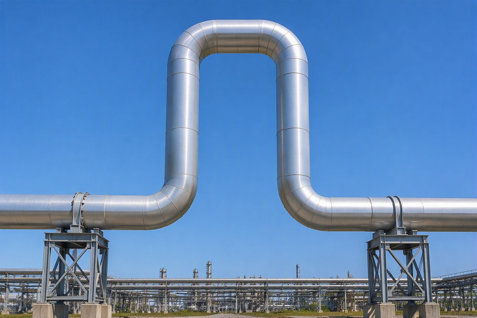
Mastering Piping Expansion Loop Design for Industrial Facilities
In my twenty years leading piping engineering design for major processing plants, managing thermal growth has always been one of the most critical mechanical integrity challenges. When high-temperature fluids surge through carbon steel or alloy piping, the metal expands linearly, exerting massive reaction forces against terminal equipment like pumps, compressors, and pressure vessels. Rather than risking catastrophic nozzle overstress or relying on maintenance-heavy sliding joints, I routinely specify a dedicated piping expansion loop to convert axial growth into safe, predictable bending moments.
Designing these configurations requires a rigorous understanding of flexibility analysis, material yield strengths, and the governing requirements of ASME B31.3 Process Piping. Whether you are routing high-pressure steam lines across elevated pipe racks or heavy crude transfer headers in a refinery, mastering loop geometry prevents premature fatigue failure and piping system collapse.
Key Engineering Takeaways
- Absorbs thermal growth entirely through elastic material flexibility rather than mechanical sliding devices.
- Eliminates bellows maintenance liabilities and sudden catastrophic pressure boundary failures in critical service lines.
- Governed by ASME B31.3 stress range reduction factors and flexibility factor equations.
- Requires precise placement of anchors, directional guides, and low-friction shoe supports to prevent line binding.
Thermal Stress Analysis and Sizing in a Piping Expansion Loop
When a high-temperature fluid enters an industrial pipeline, the metal lattice expands uniformly in all directions. If the pipe is anchored at both ends without adequate routing freedom, thermal growth creates an unconstrained compressive force. According to Hooke’s Law and elementary mechanics of materials, the total thermal growth to absorb across an unguided span is calculated using the linear expansion equation:
delta = L * alpha * (T2 – T1)
Where delta represents total linear growth in inches or millimeters, L is the active pipe length between anchors, alpha is the mean coefficient of thermal expansion for the specific material grade, T2 is the maximum operating temperature, and T1 is the ambient installation temperature. In my design reviews, ignoring ambient extremes or utilizing incorrect expansion coefficients routinely leads to severe overstress conditions.
To neutralize this linear growth safely, the engineer must introduce a perpendicular offset, forming the classic U-shaped configuration. This geometry converts axial thermal thrust into bending stress across three primary legs: the incoming run leg, the transverse header leg, and the returning leg. The overall width and height of this configuration must be proportioned correctly to keep peak bending stresses well below allowable stress ranges defined by ASME B31.3.
Governing ASME B31.3 Stress Compliance Criteria
Compliance with ASME B31.3 Section 319 requires that the displacement stress range (Sa) does not exceed the allowable displacement stress range (SA). The code formula for allowable stress range incorporates ambient and operating stress levels, cyclic life reduction factors, and material yield properties:
SA = f * (1.25 * Sc + 0.25 * Sh)
In this expression, Sc is the basic allowable stress at ambient temperature, Sh is the basic allowable stress at operating temperature, and f is the stress range factor derived from the anticipated equivalent full temperature cycles over the operational plant lifespan. For standard process lines experiencing up to 7,000 thermal cycles, f equals 1.0. For severe cycling services exceeding 250,000 cycles, the factor drops significantly, demanding larger loops or more flexible configurations.
Critical Design Warning: Torsional Overstress in 3D Layouts
When a piping expansion loop shifts out of a single two-dimensional plane into a three-dimensional rack transition, thermal growth can introduce severe torsional twisting into intersecting branch lines. Never rely on rule-of-thumb sizing tables for multi-plane routing. Always run a comprehensive finite element stress analysis using software like Caesar II to evaluate torsional shear stresses (St) against code limits.
Mathematical Sizing Rules and Proportions
While computer stress software is mandatory for final sign-off, preliminary sizing in the conceptual layout phase relies on standard engineering approximations. To calculate the required loop height (h) for a given anchor span length (L) and thermal expansion (delta), piping designers use empirical flexibility formulas derived from beam bending theory:
h = sqrt( (3 * E * D * delta) / (2 * Sa) )
Where E represents the modulus of elasticity at operating temperature, D is the nominal outer diameter of the pipe, delta is thermal growth, and Sa is allowable stress. In practice, if the calculated loop height becomes too large for standard structural pipe rack tiers, designers split the thermal growth across two smaller loops or introduce symmetrical offset z-bends.
Support, Guide, and Anchor Placement Mechanics
The mechanical effectiveness of any thermal expansion loop depends entirely on precise structural support positioning. Improperly placed guides will lock the pipe, causing lateral bowing, high frictional resistance, and localized flange leakage.
- Main Anchors: Designed to withstand full thermal thrust forces, frictional drag loads, and internal pressure thrusts. Placed at fixed equipment nozzles or midway between expansion loops.
- Directional Guides: Positioned immediately adjacent to the loop legs to ensure thermal growth feeds directly into the loop without lateral deflection or snake-like buckling.
- Low-Friction Shoes: Installed on sliding supports beneath the loop header to minimize axial friction force (F = mu * W), preventing uncalculated bending moments.
By adhering strictly to these sizing principles, material specifications, and support standards, piping engineers ensure decades of reliable, leak-free operation across the most demanding industrial process environments.
Advantages & Disadvantages
Key Engineering Advantages
- Zero maintenance requirement over the operational lifespan, unlike sliding bellows or packed slip joints.
- Eliminates catastrophic pressure boundary blowout risks inherent in mechanical expansion joints.
- Maintains full internal pipe cross-section without flow turbulence or pressure drop penalties.
- Fabricated directly from standard pipe stock and welding fittings, matching base metal metallurgy.
- Inherently compliant with high-cycle fatigue limits under rigorous ASME B31.3 design rules.
Key Engineering Disadvantages
- Consumes substantial spatial footprint and structural real estate on pipe racks and ground sleepers.
- Increases total installed piping material costs due to additional pipe footage, elbows, and welds.
- Creates significant pressure drop increases resulting from added directional changes and fitting losses.
- Imposes complex structural loading requirements on pipe rack framing and support steel.
- Requires precise engineering analysis to prevent localized sagging and pocketing in wet gas or draining services.
Real-World Applications
High-Pressure Steam Distribution Headers
Power generation and petrochemical facilities distribute superheated steam at temperatures exceeding 500 degrees Celsius across extensive outdoor pipe racks. Installing large vertical U-shaped loops absorbs massive thermal elongation, preventing destructive bending forces from buckling header branches or fracturing turbine inlet flanges.
Cryogenic Liquefied Natural Gas Transfer Lines
LNG liquefaction plants handle extremely low temperatures down to minus 162 degrees Celsius, causing metals to contract severely rather than expand. Specialized horizontal expansion loops integrated into stainless steel transfer lines accommodate extreme thermal contraction, maintaining structural integrity without thermal shock failure.
Refinery Catalytic Cracker Hot Catalyst Lines
Fluid catalytic cracking units circulate abrasive catalyst solids at severe high temperatures through large-diameter refractory-lined piping. Because mechanical bellows would quickly erode and jam under solid particulate flow, engineered geometric expansion loops are the only viable solution for thermal control.
Long-Distance Cross-Country Crude Oil Pipelines
Buried and above-ground crude transport pipelines experience massive seasonal temperature swings between winter freezing and blistering summer sun. Overhead expansion loops and engineered zigzag offset configurations allow buried or trestle-supported lines to shift freely without placing excessive stress on girth welds.
Chemical Plant Reactive Acid Transfer Systems
Manufacturing facilities handling highly corrosive acids in alloy piping cannot tolerate mechanical expansion joint seal failures or packing leaks. All-welded expansion loops constructed from specialized austenitic stainless steels provide absolute containment security for aggressive chemical streams.
Piping Expansion Loop Sizing and Dimensional Parameters
Proper sizing of an outdoor industrial piping expansion loop requires careful calculation of thermal growth, anchor loads, and flexibility factors. In my engineering practice, underestimating the required loop length (L) leads to excessive bending stresses that violate ASME B31.3 Process Piping code limits. The following engineering data table outlines standard dimensional ratios, suggested loop leg lengths based on anchor spacing, and corresponding stress intensification factors (SIFs) for typical carbon steel piping networks operating at elevated temperatures.
When evaluating these parameters for process lines, engineers must cross-reference operating temperatures against material yield strengths. The tabulated data below serves as a preliminary sizing baseline for standard 90-degree bend loops before conducting finite element stress analysis.
| Nominal Pipe Size | Approximate Loop Height (H) | Recommended Loop Width (W) | Max Anchor Load Capacity | ASME B31.3 Compliance Code |
|---|---|---|---|---|
| 4-inch NPS (DN100) | 1,800 mm | 1,200 mm | 15.4 kN | Chapter II, Section 319 |
| 8-inch NPS (DN200) | 2,600 mm | 1,800 mm | 38.2 kN | Chapter II, Section 319 |
| 12-inch NPS (DN300) | 3,500 mm | 2,400 mm | 74.5 kN | Chapter II, Section 319 |
| 16-inch NPS (DN400) | 4,200 mm | 3,000 mm | 112.0 kN | Chapter II, Section 319 |
Note: Values are calculated assuming standard carbon steel pipe (ASTM A106 Gr. B) operating at a temperature differential of 200 degrees Celsius with uniform support friction coefficients.
Technical Mapping & Specifications Matrix
To maintain rigorous quality assurance during industrial piping design, engineers rely on structured technical matrices that map physical phenomena to specific engineering standards and analytical tools. This entity matrix correlates the core parameters governing thermal displacement with industry benchmarks and software requirements.
Reviewing these relationships helps project teams identify critical inputs required for finite element modeling and physical constructability reviews. Each entity represents a distinct engineering constraint managed during the lifecycle of an elevated loop design.
| Engineering Entity | Governing Standard / Code | Primary Physical Parameter | Design Verification Method |
|---|---|---|---|
| Thermal Expansion Growth | ASME B31.3 Section 319 | Coefficient of Thermal Expansion (alpha) | Caesar II / Hand Calculations |
| Structural Support Trestles | ASCE 7 / AISC 360 | Axial and Lateral Reactions (Fx, Fy, Fz) | STAAD.Pro / SAP2000 Finite Element |
| Pipe Guides & Shoes | MSS SP-58 | Frictional Resistance and Clearance | Physical Site Inspection / Load Test |
| Weldment Stress Intensification | AWS D1.1 / ASME Section VIII | Fatigue and SIF Multipliers (i-factors) | Radiographic Testing & FEA Stress Probing |
Matrix utilization ensures seamless coordination between piping stress engineers and structural steel designers during multidisciplinary design reviews.
Site Verification Checklist for Expansion Loop Installation
Site verification of an outdoor piping expansion loop before commissioning requires a systematic inspection protocol to ensure unhindered thermal movement. In my site experience, neglecting alignment checks on support trestles leads to premature pipe shoe binding and severe piping failure. The verification checklist below details essential validation steps required by piping quality control engineers prior to hydrotesting and startup.
Pre-Commissioning Inspection Checklist
- Anchor Rigidity Verification: Confirm that primary structural anchors adjacent to the loop are fully grouted, torqued, and compliant with structural drawings before piping is loaded.
- Guide Alignment Check: Inspect all axial pipe guides along the approach legs to ensure proper spacing and zero lateral binding during initial cold position.
- Support Shoe Clearance: Verify that sliding pipe shoes rest completely on wear plates and that no temporary shipping clamps or tie-rods remain attached.
- Cold Spring Verification: Measure gap discrepancies if cold spring is specified in the design package to ensure correct pre-stressing force application.
- Drain and Vent Placement: Confirm low-point drains and high-point vents are correctly installed on the loop vertical legs to prevent water accumulation or air pockets.
- Clearance Envelope Inspection: Check that overhead cable trays, access platforms, and adjacent structural steel maintain minimum required clearance throughout full thermal travel.
Every item on this checklist must be signed off by the lead piping engineer and quality inspector in accordance with ASME B31.3 Quality Control Requirements prior to system pressurization.
Field Case Study: Solving Thermal Binding in an Elevated Petrochemical Loop
On a recent refinery expansion project handling high-temperature hydrocarbon vapors, an elevated U-shaped expansion loop experienced severe binding and localized pipe buckling during initial steam-out testing. The incident highlighted critical oversight in support design and field alignment tolerances.
Field Engineering Problem Encountered
During thermal commissioning, the 12-inch process line failed to expand freely into the overhead U-loop, resulting in dangerous bowing of the lower horizontal leg.
- Contractors mistakenly welded rigid slide plates instead of low-friction PTFE sliding pads beneath the loop support shoes.
- Approach pipe guides were installed with zero clearance tolerances, preventing lateral thermal migration.
- Structural trestle deflection under operating loads exceeded the initial finite element model predictions.
- Insulation cladding brackets restricted vertical travel by catching on adjacent structural framing.
Engineering Outcome and Remediation
Immediate corrective actions restored operational flexibility and brought the piping system into full compliance with ASME B31.3 Stress Limits.
- Replaced all binding slide plates with approved self-lubricating PTFE composite wear pads.
- Adjusted pipe guide gap clearances to allow 5 mm of lateral play on each side of the guide bracket.
- Added structural stiffeners to the support trestle to increase lateral rigidity and reduce deflection by 60 percent.
- Modified insulation standoff brackets to clear adjacent steel members throughout the full 150-millimeter thermal displacement range.
Recommendation: Always perform a cold-to-hot walk audit with laser displacement meters during initial plant startup to catch support binding before permanent plastic deformation occurs.
Frequently Asked Engineering Questions
How do I determine the correct leg length for a piping expansion loop?
- Compute unrestrained thermal movement using maximum and minimum design temperatures.
- Apply standard flexibility equations factoring in pipe outer diameter and stress range reduction factors.
- Ensure the height-to-width ratio of the loop sits between 1.5 to 2.0 for optimum flexibility.
- Verify that resulting anchor forces do not exceed equipment nozzle ratings.
When should I choose an expansion loop instead of a mechanical bellows?
- Expansion loops contain no pressure thrust forces, eliminating heavy structural sliding anchor requirements.
- Bellows introduce single points of catastrophic failure requiring periodic inspection under ASME standards.
- Geometrical loops require significant real estate but offer indefinite fatigue life if properly supported.
- Bellows are strictly preferred when plot space is severely restricted inside modular process units.
How do directional pipe guides function in an expansion loop layout?
- Install the first set of axial guides within four pipe diameters of the loop anchor points.
- Use secondary guides at progressively larger intervals to prevent lateral buckling of long spans.
- Ensure guide clearances permit smooth axial sliding without binding against structural steel members.
- Check that low-friction slide plates are specified for high-temperature insulated carbon steel lines.
What causes premature failure in outdoor industrial piping expansion loops?
- Locking up of sliding shoes due to corrosion or improper installation creates high localized bending stresses.
- Failing to account for wind-induced dynamic loads combined with thermal cycling accelerates fatigue.
- Unauthorized field routing changes that shorten loop legs drastically raise operational stress intensification.
- Poor drainage design inside low points of loops leads to water hammer or accelerated internal corrosion.
How does software like Caesar II verify piping expansion loop designs?
- Input exact temperature load cases, pressure ratings, and insulation weight densities into the node model.
- Review code compliance output reports against ASME B31.3 Chapter II allowable stress ranges.
- Analyze restraint reaction loads to confirm structural steel trestles can handle transferred thrust forces.
- Iterate loop dimensions digitally until stress ratios drop comfortably below unity across all operating conditions.
In my two decades of executing complex process plant designs, I have observed that field shortcuts during pipe support installation routinely cause more failures than initial thermal calculation errors. When laying out outdoor elevated expansion loops, make these definitive engineering judgment calls:
- If plot space on your pipe rack allows, always choose a three-dimensional or horizontal U-loop over complex multi-plane offsets to simplify structural steel detailing and streamline erection.
- If operating temperatures exceed 300 degrees Celsius on carbon steel lines, specify PTFE slide plates with stainless steel backing pads at all guide locations to prevent friction lock-up and subsequent over-stressing of the loop legs.
- If wind loading in coastal or open-grade industrial facilities creates significant lateral sway, install rigid cross-bracing on the upper support trestles rather than oversized pipe guides to maintain pure axial thermal growth.
- If initial stress analysis shows anchor reactions exceeding equipment nozzle allowances by more than 15 percent, increase the loop height rather than reducing wall thickness to preserve pressure containment safety margins.
Complete Course on
Piping Engineering
Check Now
Key Features
- 125+ Hours Content
- 500+ Recorded Lectures
- 20+ Years Exp.
- Lifetime Access
Coverage
- Codes & Standards
- Layouts & Design
- Material Eng.
- Stress Analysis
