Mastering Pipe Wall Thickness Calculation in Process Plant Design
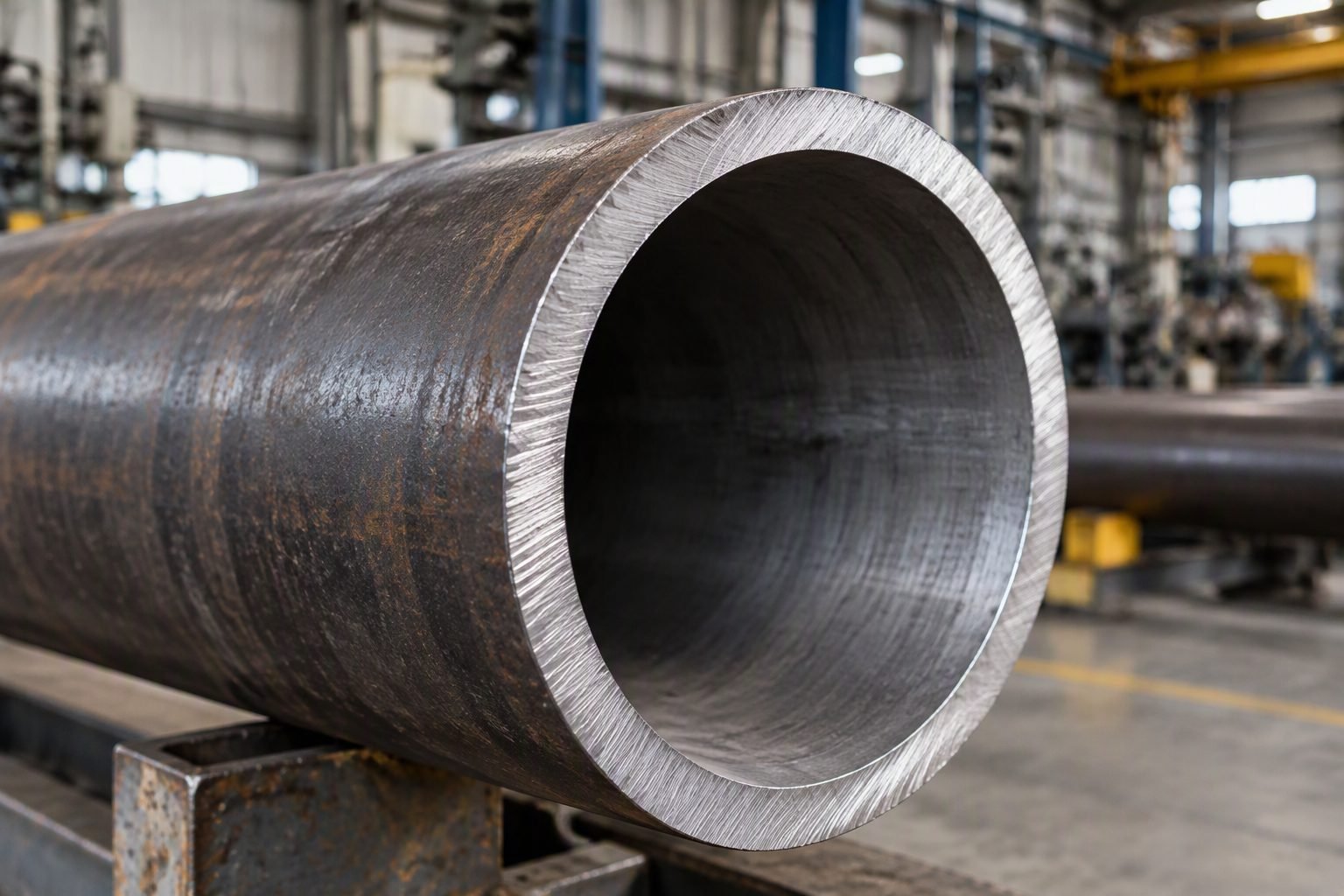
In my two decades of reviewing piping engineering deliverables across major refinery and petrochemical expansions, I have found that no single calculation causes more fabrication rework than an improperly sized pipe wall. When you look at a freshly cut industrial steel pipe end on the shop floor, the exposed cross-section tells a critical story. It reveals the exact structural steel dimension that separates a safe containment envelope from a catastrophic containment failure.
Junior engineers often rely blindly on software defaults, missing the nuances of manufacturing variations and corrosive operating environments. To protect plant personnel and asset integrity, you must master the fundamental mechanics of pressure design, including how to correctly incorporate mill tolerance and corrosion allowance into every sizing sheet.
Key Engineering Takeaways
- Nominal pipe size (NPS) never equals actual internal or external structural wall thickness.
- ASME B31.3 mandates a standard 12.5% negative mill fabrication tolerance for rolled or seamless carbon steel pipe.
- Corrosion allowance must be added directly to the calculated pressure thickness before selecting standard schedule pipe.
- Weld joint quality factors (E) and temperature derating coefficients directly multiply required baseline thickness.
ASME B31.3 Pipe Wall Thickness Calculation Methodology
When performing a rigorous pipe wall thickness calculation, you must start with the baseline hoop stress equations outlined in ASME B31.3 Paragraph 304.1. The internal design pressure (P) acts against the internal radius or diameter, creating tensile circumferential stresses across the pipe wall. For standard straight cylindrical pipe where t < D/6 or P < 0.385SE, the baseline pressure design thickness (t_m) is calculated using the Barlow formula variant.
The standard formula is expressed as t = (P · D/2 · (S · E + P · y)), where P is internal design gage pressure, D is outside diameter of the pipe, S is allowable stress from ASME B31.3 Appendix A, E is longitudinal weld joint quality factor, and y is a temperature-dependent coefficient ranging from 0.4 for austenitic stainless steels at lower temperatures up to 0.7 for high-temperature ferritic steels.
Incorporating Mill Tolerance and Corrosion Allowance
The mathematical pressure thickness (t) derived from the Barlow equation represents only the net metal required to resist hoop stress under hydrostatic load. It does not account for manufacturing anomalies or metal loss over the operating life of the facility. To transition from raw pressure thickness to the nominal ordered thickness, you must layer in fabrication and degradation factors.
First, account for the negative mill tolerance (c_m). Per standard ASTM manufacturing specifications such as A53 and A106, seamless and electric resistance welded carbon steel pipes possess a permitted negative wall thickness variation of 12.5%. Therefore, you must divide your pressure thickness plus corrosion allowance sum by (1 – 0.125) or multiply by 1.143 to ensure that even the thinnest localized spot on the pipe wall meets minimum structural requirements.
Critical Engineering Warning: Threaded and Grooved Allowances
If your piping design incorporates threaded joints, you must add the threading depth (h) or structural groove depth to the sum of corrosion allowance before applying the mill tolerance factor. Neglecting thread depth drastically increases the risk of premature thread-root cracking and catastrophic pressure boundary leakage.
Similarly, for straight threaded pipe, ASME B31.3 requires an additional structural allowance equal to the depth of the thread (c_0), ensuring that the remaining wall beneath the root of the thread satisfies hoop stress limits.
Step-by-Step Calculation Procedure for Piping Engineers
To execute a bulletproof wall thickness calculation on your next project, follow this structured engineering workflow. Skipping any of these sequential checkpoints during stress analysis reviews can lead to severe audit non-conformances.
- Step 1: Gather Operating Parameters: Define maximum allowable working pressure (MAWP), design temperature, fluid corrosivity, and expected plant service life in years.
- Step 2: Select Material and Allowable Stress: Choose the appropriate ASTM specification and look up allowable stress (S) at design temperature from ASME Section II Part D.
- Step 3: Determine Weld Joint Factor (E): Assign factor E based on nondestructive examination (NDE) extent, ranging from 0.60 for furnace butt-welded pipe up to 1.00 for fully radiographed seamless pipe.
- Step 4: Compute Pressure Thickness (t): Apply the ASME B31.3 Eq. 3a formula using outside diameter and temperature coefficient y.
- Step 5: Add Corrosion Allowance (CA): Sum the process-specific metal loss rate multiplied by operating years to t.
- Step 6: Apply Mill Tolerance (c_m): Divide the intermediate sum by 1.0 – text{Mill Tolerance Fraction} to obtain minimum nominal wall thickness (t_m).
- Step 7: Select Commercial Schedule: Compare t_m against standard pipe schedules in ASME B36.10M or B36.19M and select the next heavier standard commercial wall thickness.
By adhering rigorously to this protocol, you eliminate guesswork and ensure your piping networks comply fully with international pressure equipment directives. Always document every input variable on your formal calculation calculation sheets for third-party jurisdictional review.
Advantages
- Guaranteed Structural Integrity: Explicitly accounts for internal pressure loads, preventing catastrophic burst failures during high-stress process upsets.
- Regulatory Compliance: Meets strict legal mandates set by ASME B31.3 and international pressure vessel authorities, reducing liability.
- Long-Term Corrosion Protection: Incorporating explicit corrosion allowances prevents premature wall thinning from aggressive chemical streams.
- Fabrication Safety Margin: Factoring in 12.5% mill tolerance ensures pipe segments never fall below minimum allowable thickness after rolling.
- Optimized Material Selection: Prevents over-engineering while ensuring lighter schedules are not mistakenly installed in high-pressure services.
Disadvantages
- Increased Capital Expenditure: Selecting heavier pipe schedules due to conservative corrosion allowances increases initial material procurement costs.
- Added Structural Weight: Thicker pipe walls substantially increase overall piping system deadweight, requiring heavier pipe rack structural steel supports.
- Fabrication Complexities: Thicker materials require preheat and post-weld heat treatment (PWHT) per ASME B31.3 Table 331.1.1, raising fabrication labor costs.
- Reduced Flow Capacity: Increased internal wall thickness marginally decreases internal cross-sectional flow area for a given nominal pipe size.
- Calculation Complexity: Manual iterative sizing requires meticulous tracking of multiple variables, increasing the risk of human calculation error.
High-Pressure Hydrocracker and Reformer Unit Piping
In modern petroleum refineries, hydroprocessing units operate at extreme pressures exceeding 150 bar and temperatures above 450 degrees Celsius. Performing accurate wall thickness calculations under ASME B31.3 High Pressure Limits (Chapter IX) is vital to prevent high-temperature hydrogen attack (HTHA) and catastrophic rupture.
Engineers must factor in alloy-specific creep properties, hydrogen embrittlement allowances, and strict mill tolerances to select heavy-wall Chrome-Moly (ASTM A335 Gr. P22/P91) piping assemblies.
Sour Gas Gathering and Transmission Pipelines
Upstream oil and gas facilities transporting multiphase hydrocarbons containing hydrogen sulfide (H_2S) and carbon dioxide (CO_2) face severe internal electrochemical corrosion. Wall thickness calculations must integrate aggressive corrosion allowances coupled with NACE MR0175/ISO 15156 material hardness limits.
This ensures that despite localized pitting and sulfide stress cracking threats, the remaining metallic cross-section retains adequate burst strength throughout the 25-year design life of the field asset.
Supercritical Power Plant Main Steam Lines
Thermal power stations operating with supercritical steam cycles push boiler feedwater and main steam piping to extreme thermal and pressure limits. Piping designers utilize rigorous ASME B31.1 Power Piping formulas to determine required wall thicknesses for austenitic stainless steel and nickel-alloy piping.
Calculations must account for thermal expansion stress ranges, cyclic fatigue, and metal thinning due to high-velocity water droplet erosion in turbine extraction lines.
Cryogenic Liquefied Natural Gas (LNG) Transfer Systems
Liquefied natural gas facilities handling fluid temperatures down to minus 162 degrees Celsius require careful wall sizing to manage low-temperature brittle fracture risks and thermal shock during startup. Although corrosion allowances are minimal in dry hydrocarbon services, mill tolerance and structural design margins remain critical.
Engineers apply ASME B31.3 rules alongside ASTM A312 austenitic stainless steel specifications to size transfer lines capable of withstanding severe thermal contraction loads without wall thinning failures.
High-Purity Chemical and Acid Distribution Headers
Chemical processing plants handling concentrated sulfuric acid, hydrochloric acid, or caustic soda experience aggressive uniform and localized wall thinning. Wall thickness calculations must integrate aggressive chemical corrosion rates determined via coupon testing or NACE corrosion data databases.
Lined piping systems and exotic alloy headers (ASTM B622 Hastelloy or Alloy 20) are sized meticulously to ensure structural containment even after years of active chemical erosion.
ASME B31.3 Pressure Design Variables and Calculation Constants
When executing a rigorous pipe wall thickness calculation, engineers must reference standardized tables for internal pressure design, material stress values, and joint efficiency factors. The following engineering data table outlines standard parameters specified under ASME B31.3 Process Piping, providing the exact variables required to determine nominal and minimum structural walls without underestimating fabrication thinning allowances.
Each parameter directly influences the governing hoop stress equation. Reviewing these standard values prevents costly field re-routing, material downgrades, and hydrostatic test failures during pre-commissioning walkdowns.
| Parameter Symbol | Description | Standard Code Reference | Typical Design Value / Range |
|---|---|---|---|
| P | Internal Design Gauge Pressure | ASME B31.3 Para. 301.2 | Operating pressure plus static head buffer |
| S | Allowable Stress in Tension from Material Table | ASME B31.3 Table A-1 | Dependent on material grade (e.g., 20,000 psi for ASTM A106 Gr. B) |
| E | Quality Factor of Longitudinal Weld Joint | ASME B31.3 Table 302.3.4 | 0.85 to 1.00 (1.00 for seamless pipes) |
| Y | Coefficient for Temperature-Dependent Material | ASME B31.3 Table 304.1.1 | 0.4 to 0.7 depending on temperature and alloy |
| c | Sum of Mechanical Allowances and Corrosion Buffer | ASME B31.3 Para. 304.1.1 | Typically 1.5 mm to 3.2 mm based on fluid service |
| W | Mill Tolerance Factor (Standard Manufacturing Allowance) | ASTM A53 / A106 Specs | 12.5% reduction below nominal thickness |
Note: All calculated minimum thickness values must be increased by the mill tolerance percentage before selecting the final commercial schedule size from standard pipe charts.
Technical Mapping & Specifications Matrix
To maintain absolute traceability across multi-discipline engineering packages, piping teams utilize an entity mapping matrix. This matrix connects physical inspection terms, metallurgical standards, and mathematical variables used during code compliance reviews for high-pressure facilities.
Cross-referencing these entities ensures that process design deliverables align perfectly with procurement specifications, non-destructive examination (NDE) procedures, and shop fabrication tolerances.
| Entity Category | Structural Acronym | Physical Parameter & Unit | Governing Standard Reference |
|---|---|---|---|
| Hoop Stress Boundary | SH | Circumferential stress limit (psi / MPa) | ASME B31.3 Chapter II |
| Mill Reduction Limit | MT | Fabrication negative tolerance percentage (%) | ASTM A53 / A106 |
| Corrosion Allowance | CA | Sacrificial metal thickness layer (mm / inches) | NACE MR0175 / ISO 15156 |
| Nominal Wall Thickness | TNOM | Catalogue pipe wall dimension (mm / inches) | ASME B36.10M / B36.19M |
| Hydrostatic Test Pressure | HTP | Shop or field proof test pressure (psi / bar) | ASME B31.3 Para. 345.4 |
Mastering this entity framework ensures seamless data exchange between piping stress analysis packages (CAESAR II) and mechanical material requisition databases.
Site Verification Checklist for Pipe Wall Thickness
Verifying incoming steel pipe shipments and fabricated spool pieces against calculated pressure requirements prevents catastrophic containment failures. In my experience, relying solely on mill test certificates without physical verification exposes projects to severe compliance risks.
Use the structured verification framework below during incoming material inspection and shop pre-welding audits to ensure strict compliance with ASME B31.3 standards.
Fabrication Yard and Site Inspection Protocol
-
1. Ultrasonic Thickness (UT) Spot Check: Measure actual wall thickness at four quadrants across both pipe ends using calibrated UT equipment, ensuring thickness does not exceed the 12.5% mill tolerance limit.
-
2. Mill Test Certificate (MTC) Review: Cross-verify heat numbers stamped on the steel pipe body against EN 10204 Type 3.1 certificates for chemical composition and tensile strength compliance.
-
3. Corrosion Allowance Verification: Confirm that the specified corrosion allowance (c) has been fully added to the pressure-derived minimum wall thickness (t) before schedule selection.
-
4. Ovality and Out-of-Roundness Inspection: Check that pipe ends maintain outer diameter tolerances within ASME B36.10M limits to prevent high radial misalignment stresses at circumferential butt welds.
-
5. Threaded and Grooved End Inspection: For connections utilizing threading, ensure that nominal wall thickness after thread cutting satisfies the absolute minimum structural thickness requirement under ASME B31.3 Para. 304.2.
All non-conforming pipe segments falling below the calculated minimum wall plus mill tolerance threshold must be quarantined and marked immediately.
Field Case Study: Real-World Application
During the construction of a high-pressure sour gas gathering facility, our engineering team encountered a critical design discrepancy involving structural wall thickness selection for carbon steel process headers operating under severe sweetening conditions.
Engineering Problem Encountered
The initial piping isometric packages specified standard Schedule 40 carbon steel pipe without accounting for negative mill tolerance and localized erosion-corrosion expected in multiphase hydrocarbon service.
- Design pressure was established at 1,480 psi at 200°F operating temperature.
- Procurement team ordered pipe based purely on the theoretical pressure equation minimum (t = 0.312text{ inches}), omitting mill tolerance.
- Incoming ultrasonic inspections revealed that received pipe batches exhibited a negative mill tolerance of 12.5%, reducing actual wall thickness to 0.273 inches.
- The specified 3.0 mm corrosion allowance was completely compromised, threatening premature wall perforation.
Definitive Engineering Outcome
By immediately halting fabrication and recalculating the nominal wall requirement incorporating full mill tolerance and corrosion allowance factors, the engineering team successfully prevented a catastrophic hydrostatic test failure.
- Upgraded all critical process lines from Schedule 40 to Schedule 80 to guarantee long-term structural integrity.
- Implemented mandatory incoming ultrasonic thickness testing protocols for all future pipe material shipments.
- Ensured full compliance with ASME B31.3 Process Piping Code requirements across the entire facility.
- Eliminated the risk of unscheduled plant downtime and avoided expensive regulatory non-compliance fines.
Recommendation: Always apply the 12.5% mill tolerance divisor in your initial pipe sizing spreadsheet to ensure commercial pipe schedules meet true operational safety requirements.
Frequently Asked Engineering Questions
How do I calculate required pipe wall thickness per ASME B31.3?
- Apply the basic Barlow or Lamé formula based on diameter-to-thickness ratios.
- Incorporate internal design pressure and maximum allowable stress values from ASME Section II.
- Factor in joint efficiency and temperature derating coefficients.
Why is 12.5% mill tolerance mandatory for steel pipe wall thickness calculation?
- Standard manufacturing specifications permit a negative wall thickness tolerance of 12.5%.
- Failing to add this margin risks operating below the minimum required pressure boundary.
- Procurement engineers must order heavier schedules to compensate for manufacturing thinning.
How do I determine the correct corrosion allowance for aggressive fluids?
- Review historical plant data and materials compatibility charts for specific chemical streams.
- Add a sacrificial metal thickness layer directly to the calculated pressure design requirement.
- Consult metallurgists when handling sour gas or high-velocity erosive slurries.
What is the difference between nominal wall thickness and schedule numbers?
- Nominal wall thickness represents the catalog dimension of the manufactured pipe wall.
- Schedule numbers loosely approximate the pressure-to-stress ratio for steel pipes.
- Engineers must map calculated minimum thicknesses to standard commercial pipe schedules.
How does thread and groove depth affect structural wall calculations?
- Add thread depth values directly into the total structural thickness summation formula.
- Account for mechanical groove depth when specifying roll-grooved or cut-grooved piping systems.
- Verify that remaining wall thickness beneath threads satisfies minimum pressure ratings.
When finalizing piping specifications on critical hydrocarbon processing units, I advise avoiding standard mill tolerance assumptions if procurement sources unknown global mills; instead, specify a verified 15% negative manufacturing allowance to guarantee long-term compliance under ASME B31.3.
- If handling high-velocity erosive catalyst slurries, select an increased corrosion allowance of 4.5 mm over base pressure requirements rather than standard allowances, because localized eddy currents accelerate wall thinning exponentially at bends.
- When ordering heavy-wall carbon steel piping for high-pressure sour service, mandate ultrasonic thickness testing upon material arrival at the fabrication yard to verify that actual mill plates meet or exceed design calculations before cutting commences.
- If transitioning from seamless pipe to electric resistance welded pipe in high-cycle vibration zones, apply a joint efficiency factor of 0.85 instead of 1.0 to prevent fatigue-induced micro-cracking along the longitudinal weld seam.
- When calculating minimum structural dimensions for threaded process connections, always add the full thread depth plus a 1.25 mm structural safety factor to compensate for stress concentration factors at the thread root.
Complete Course on
Piping Engineering
Check Now
Key Features
- 125+ Hours Content
- 500+ Recorded Lectures
- 20+ Years Exp.
- Lifetime Access
Coverage
- Codes & Standards
- Layouts & Design
- Material Eng.
- Stress Analysis
