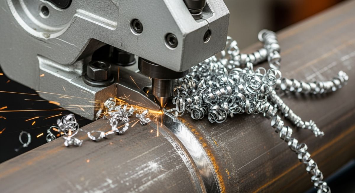
How to Select Pipe Bevelling Machines for High-Quality Welds
[Pipe Bevelling Machines]: [Mechanical tools designed to cut a precise angle or profile on the end of a pipe to prepare it for code-compliant welding in accordance with ASME B31.3 and ASME Section IX standards].
Whether you are working on high-pressure steam lines, offshore pipelines, or sanitary stainless steel tubing, the quality of your weld root pass depends entirely on the geometry of your bevel. If your root face is too thin, you risk burn-through; if your bevel angle is inconsistent, you will suffer from lack of fusion. In this guide, I will share my field experience on selecting, calibrating, and operating these machines to achieve flawless weld preparation.
Key Takeaways for Piping Engineers
- Cold cutting technology prevents thermal degradation of the pipe metallurgy, preserving the base metal properties.
- ID-mount machines offer superior stability for heavy-wall, small-to-medium diameter pipes.
- OD-mount split-frame clamshell machines allow simultaneous cutting and bevelling on existing pipelines.
- Strict adherence to ASME B31.3 joint geometries reduces weld reject rates to under one percent.
Why Use Pipe Bevelling Machines for Weld Prep?
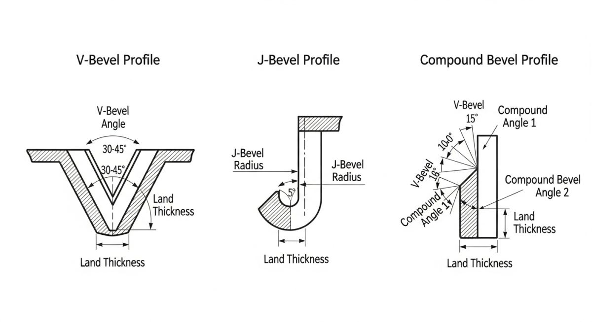
[Weld Joint Preparation]: [The process of machining pipe ends to specific geometries, such as V-bevels, J-bevels, or compound angles, to ensure full penetration welds under ASME Section VIII and B31.3 codes].
When preparing pipe ends for high-integrity welding, we must control three primary variables: the bevel angle, the root face (or land), and the root gap. Traditional thermal cutting methods like oxy-fuel or plasma torching introduce extreme heat into the pipe end. This heat alters the grain structure of the metal, creating a Heat-Affected Zone (HAZ) that is highly susceptible to cracking and stress corrosion.
Mechanical pipe bevelling machines utilize cold cutting technology. By using high-torque, low-speed carbide or high-speed steel (HSS) tool bits, these machines shave away the metal without generating significant heat. This preserves the mechanical properties of the parent metal, ensuring that the subsequent weld complies with the original material specifications of ASME B31.3.
FIELD WARNING:
Never use thermal cutting on high-alloy steels, such as duplex stainless steel or P91 chrome-moly pipes, without subsequent post-weld heat treatment (PWHT) or machining away the HAZ. Shaving off at least 1.5 mm of the thermally cut edge using a mechanical beveller is mandatory to eliminate the micro-cracks and hardened layers left by plasma or oxy-fuel cutting.
Calculating Weld Joint Volume and Bevel Geometry
To optimize weld consumable consumption and cycle times, we must calculate the cross-sectional area of the weld joint. Let us look at a standard single-V bevel with a root face (land) and root gap.
The Formula for Single-V Bevel Cross-Sectional Area:
Where:
- t = Pipe wall thickness (mm)
- f = Root face / land thickness (mm)
- g = Root gap (mm)
- theta = Half of the included bevel angle (degrees)
Let us calculate the weld area for a 12-inch Schedule 80 carbon steel pipe (ASTM A106 Grade B).
The nominal wall thickness (t) is 17.48 mm.
According to standard welding procedures, we will use a 37.5-degree bevel angle (theta = 37.5 degrees), a 1.6 mm root face (f), and a 2.4 mm root gap (g).
h = t – f = 17.48 mm – 1.6 mm = 15.88 mm
Step 2: Calculate the area of the root gap portion (A1)
A1 = h * g = 15.88 mm * 2.4 mm = 38.11 mm^2
Step 3: Calculate the area of the sloped bevel portion (A2)
A2 = h^2 * tan(37.5 degrees)
A2 = (15.88)^2 * 0.7673 = 252.17 * 0.7673 = 193.49 mm^2
Step 4: Total Cross-Sectional Area (A_total)
A_total = A1 + A2 = 38.11 mm^2 + 193.49 mm^2 = 231.60 mm^2
By knowing this cross-sectional area, we can accurately estimate the weight of the weld metal required per joint, which directly influences our choice of welding process and the required precision of our pipe bevelling machines.
ID-Mount vs. OD-Mount Bevelling Systems
In my experience, choosing between an Inside Diameter (ID) mount and an Outside Diameter (OD) mount machine depends on your workspace constraints and pipe wall thickness. ID-mount machines utilize an expanding mandrel that locks into the pipe bore. This design is exceptionally rigid, making it ideal for heavy-wall end prep and counterboring. OD-mount machines, often called split-frame or clamshell cutters, clamp onto the outside of the pipe. They are designed to split in half, allowing you to mount them anywhere along an existing pipeline to perform simultaneous cutting and bevelling.
The table below outlines the standard joint geometries and recommended machine configurations based on pipe schedule and nominal pipe size (NPS), in compliance with AWS D10.11 guidelines.
| Pipe Size (NPS) | Wall Thickness Range | Bevel Profile Type | Recommended Machine Type | Primary Advantage |
|---|---|---|---|---|
| 0.5″ to 2″ | Sch 10 to Sch 80 | 37.5° Single V | Handheld OD-Mount / Benchtop | Rapid setup, high portability |
| 2″ to 8″ | Sch 40 to Sch 160 | 37.5° Single V / 30° V | ID-Mount Mandrel | Perfect concentricity with pipe ID |
| 8″ to 24″ | Sch 80 to XXS | Compound V (37.5° + 10°) | OD-Mount Split-Frame | Simultaneous cut and bevel, heavy torque |
| 24″ and Above | Heavy Wall (> 25mm) | Narrow Gap J-Bevel | Heavy-Duty Clamshell / Auto-Track | Minimizes weld volume, reduces heat input |
This matrix maps the critical engineering parameters of pipe bevelling tools against material types and operational constraints.
| Material Class | Tool Bit Material | Cutting Speed (RPM) | Coolant Requirement | Applicable Standard |
|---|---|---|---|---|
| Carbon Steel (A106/A53) | HSS (Cobalt-coated) | 40 – 60 | Optional (Dry cutting possible) | ASME B16.25 |
| Stainless Steel (304/316) | Carbide (TiAlN-coated) | 20 – 35 | Highly Recommended (Water-soluble) | ASME B31.3 |
| Duplex / Super Duplex | Premium Carbide Grade | 10 – 20 | Mandatory (Continuous flood) | ASTM A928 |
| Chrome-Moly (P11/P22/P91) | Heavy-Duty Cobalt HSS | 15 – 30 | Recommended (Synthetic oil) | ASME Section I |
How to Calibrate Pipe Bevelling Machines Safely
[Machine Calibration]: [The systematic verification of tool bit alignment, mandrel expansion, and rotational clearance to prevent pipe wall damage and ensure precise bevel angles before machining operations begin].
Before starting any machining operation on-site, the operator must verify that the machine is securely mounted and calibrated. A loose machine can slip during cutting, destroying expensive tool bits and posing a severe safety hazard to the operator. Use this checklist to ensure safe and accurate operation.
Pre-Operation Quality & Safety Checklist
-
Verify Pipe Ovality: Measure the pipe OD and ID at 90-degree intervals. If ovality exceeds 1.5% of the nominal diameter, use an OD-tracking module to prevent uneven land thickness.
-
Inspect Mandrel Expansion (ID-Mount): Ensure all expansion blocks are clean, free of metal shavings, and fully engaged with the pipe inner wall.
-
Check Tool Bit Sharpness: Dull bits generate excessive heat and friction, leading to work-hardening of stainless steel and poor surface finish. Replace bits showing chipped edges.
-
Confirm Bevel Angle: Use a protractor gauge to verify the tool bit angle matches the welding procedure specification (WPS) before locking the tool holder.
-
Verify Air/Power Supply: For pneumatic machines, ensure the air line has an active lubricator and maintains a minimum pressure of 90 PSI (6.2 bar) under load.
Field Case Study: Real-World Application
The Problem: High Weld Reject Rates on P22 Alloy Piping
During a major refinery turnaround, a mechanical contractor was struggling with a 14% weld reject rate on 16-inch Schedule 120 P22 chrome-moly steam lines. The contractor was using hand-held grinders and thermal cutting to prepare the 37.5-degree V-bevels. Radiographic testing (RT) revealed systematic lack of root fusion and slag inclusions caused by highly inconsistent root faces (lands) and localized hardening of the pipe ends due to thermal cutting.
The Solution: Transition to OD-Mount Split-Frame Bevellers
I was brought in to audit the process. We immediately halted all hand-grinding and thermal cutting on the P22 lines. We introduced heavy-duty, pneumatic OD-mount split-frame clamshell machines equipped with cobalt HSS tool bits. We configured the machines to perform a compound bevel (37.5 degrees transitioning to 10 degrees) to reduce the total weld volume by 22%, while maintaining a precise 1.6 mm root face.
The Outcome and Engineering Recommendation
By switching to mechanical cold cutting, we eliminated the hardened heat-affected zone entirely. The split-frame machines delivered perfectly concentric bevels with a tolerance of +/- 0.1 mm on the root face. The weld reject rate dropped from 14% to a mere 0.4% over the next 120 joints.
My recommendation for any project involving heavy-wall alloy piping is to mandate mechanical cold-cutting end prep in the project specifications. The initial investment in renting or purchasing split-frame machines is recovered within the first ten welds by eliminating costly weld repairs and downtime.
Frequently Asked Engineering Questions
What is the difference between a V-bevel and a J-bevel?
Why is cold cutting preferred over thermal cutting for pipe end prep?
How do I choose between pneumatic and hydraulic drive motors?
What is a compound bevel and when should it be used?
Can I bevel stainless steel pipes dry, or do I need coolant?
How does pipe ovality affect the bevelling process?
Complete Course on
Piping Engineering
Check Now
Key Features
- 125+ Hours Content
- 500+ Recorded Lectures
- 20+ Years Exp.
- Lifetime Access
Coverage
- Codes & Standards
- Layouts & Design
- Material Eng.
- Stress Analysis



