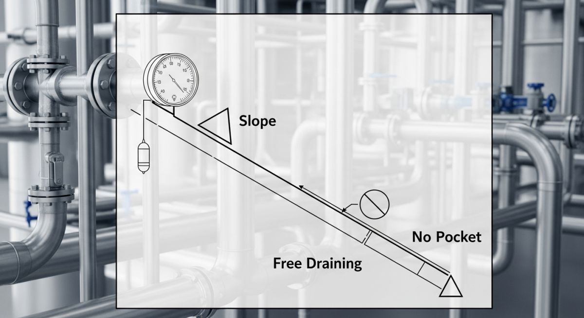
Understanding Slope, Free Draining, Gravity Flow, and No Pocket in P&ID
In my 20+ years of piping engineering, I have seen minor drafting oversights on a P&ID lead to catastrophic water hammer, accelerated localized corrosion, and complete plant shutdowns. When a process engineer writes “Free Draining” or “No Pocket” on a schematic, it is not a mere suggestion—it is a strict geometric mandate that the piping designer must translate into physical reality. Let us break down exactly what these terms mean, how they differ, and how to execute them on the shop floor.
Key Engineering Takeaways
- Slope requires a continuous, calculated physical incline (e.g., 1:100) to move fluids.
- Free Draining ensures no liquid remains trapped when the system is isolated or depressurized.
- Gravity Flow relies entirely on static head to transport process fluids without pumps.
- No Pocket eliminates any U-shaped low points where condensate or corrosive phases can pool.
Demystifying Slope, Free Draining, Gravity Flow, and No Pocket in P&ID
To execute these requirements correctly, we must first establish the physical and thermodynamic differences between each designation. While they all deal with gravity and fluid accumulation, their hydraulic behaviors and design rules are distinct.
1. Slope (SL)
A sloped line is designed with a continuous, uniform incline along its horizontal run. The primary objective is to facilitate the movement of liquids (or condensed vapors) in a specific direction. In my practice, I specify slope as a ratio or percentage. For example, a 1:100 slope means the pipe drops 1 unit vertically for every 100 units of horizontal run. This is common in flare headers, steam condensate lines, and sewer systems.
2. Free Draining (FD)
Free draining means that the piping configuration must allow all liquid to drain out completely under the influence of gravity, leaving no residual liquid in the line. This is a critical safety requirement for lines carrying corrosive, toxic, or reactive chemicals, as well as utility lines subject to freezing. Unlike a simple sloped line, a free-draining line must not contain any intermediate high or low points, and it must drain directly into a vessel, header, or designated low-point drain valve.
3. Gravity Flow (GF)
Gravity flow is a hydraulic condition where fluid transport is driven entirely by the difference in static elevation head between the source and the destination. The driving force is calculated as the product of elevation head, fluid density, and gravitational acceleration. The piping designer must size the line such that the available static head is greater than the total frictional pressure drop at the design flow rate. Gravity flow lines are typically larger in diameter to minimize frictional losses.
4. No Pocket (NP)
A “pocket” is any U-shaped or low-point configuration in a piping run where liquid can accumulate (in a gas system) or where vapor can become trapped (in a liquid system). A “No Pocket” requirement means the line must be routed horizontally or vertically in a way that prevents these traps. In gas lines, pockets lead to liquid accumulation, which can cause severe water hammer or slug flow. In liquid lines, vapor pockets can cause air binding, restricting flow or causing pump cavitation.
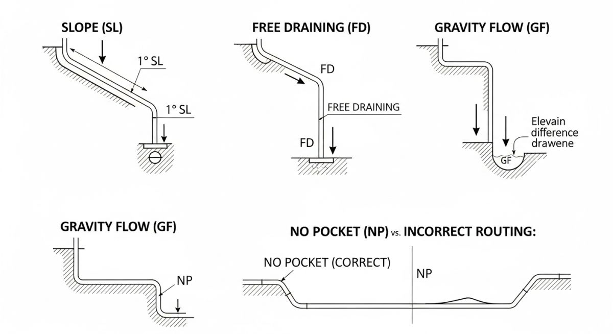
When designing these systems, we must adhere to international standards such as ASME B31.3 Process Piping and API RP 14E for design velocity and pressure drop limits.
| Designation | Typical Slope / Geometry | Primary Process Application | Key Design Rule | Code Reference |
|---|---|---|---|---|
| Slope (SL) | 1:100 to 1:200 (1% to 0.5%) | Flare headers, steam condensate return | Continuous slope to knockout drum | ASME B31.3 |
| Free Draining (FD) | Sloped toward vessel/header | Compressor suction lines, vent headers | No low points, use eccentric reducers | API RP 14E |
| Gravity Flow (GF) | Calculated based on hydraulics | Cooling water return, drain systems | Available head must exceed friction loss | ASME B31.3 |
| No Pocket (NP) | Horizontal or sloped | Gas analyzer loops, pump suction | Avoid vertical loops, use FOB/FOT reducers | ASME B31.3 |
| Entity / Acronym | Physical Parameter | Design Constraint | Mitigation Strategy | Standard Reference |
|---|---|---|---|---|
| FOB (Flat on Bottom) | Eccentric reducer orientation | Liquid accumulation in gas lines | Keep bottom of pipe flat | ASME B31.3 |
| FOT (Flat on Top) | Eccentric reducer orientation | Vapor pocketing in liquid lines | Keep top of pipe flat | ASME B31.3 |
| Slug Flow | Two-phase flow regime | High velocity liquid slugs | Maintain continuous slope, eliminate pockets | API RP 14E |
| Water Hammer | Hydraulic shock wave | Condensate accumulation in steam lines | Install steam traps and slope lines | ASME B31.3 |
How to Verify Piping Isometric Drawings?
Before releasing any piping isometric drawing for fabrication, I require my design team to run through this rigorous checklist. This prevents costly field re-work and ensures compliance with process safety standards.
Design Verification Checkpoints
-
[ ]
Verify slope direction arrows on the isometric match the P&ID flow and drain requirements. -
[ ]
Confirm all horizontal reducers in “Free Draining” lines are eccentric with the correct orientation (FOB for gas, FOT for liquid). -
[ ]
Check that control valve stations in gravity flow lines do not create high-point vapor pockets. -
[ ]
Ensure steam header drip legs are located at the lowest points of the sloped run. -
[ ]
Validate that the physical slope angle (e.g., 1:100) is explicitly dimensioned on the isometric drawing. -
[ ]
Confirm that no vertical loops or “U-bends” exist in lines designated as “No Pocket”.
Field Case Study: Real-World Application
The Problem
During the commissioning of a natural gas processing plant, a compressor suction line designated as “Free Draining” on the P&ID experienced severe liquid carryover. This resulted in repeated compressor trips and damage to the first-stage impeller blades. Upon field inspection, I discovered that the piping designer had routed the line with a horizontal run containing three concentric reducers and a minor vertical loop to clear a structural steel beam. This created a series of liquid pockets where heavy hydrocarbons accumulated during low-flow periods, only to be swept into the compressor as a massive liquid slug when the flow rate increased.
The Outcome
I ordered an immediate shutdown and hot-work modification of the suction piping. We replaced the concentric reducers with eccentric flat-on-bottom (FOB) reducers and rerouted the line to eliminate the vertical loop, establishing a continuous 1:150 slope directly back to the suction scrubber. The modification completely eliminated liquid accumulation, and the compressor has operated without a single liquid-carryover trip for over five years.
My direct recommendation: Always perform a physical walkdown of critical lines using the isometric drawings and P&ID side-by-side before releasing spools for fabrication.
Frequently Asked Engineering Questions
Design Rules for Slope, Free Draining, Gravity Flow, and No Pocket in P&ID
What is the difference between Slope and Free Draining?
Why is “No Pocket” critical for compressor suction lines?
How do you calculate the minimum slope for gravity flow?
Can a sloped line still have a pocket?
What are the consequences of ignoring “No Pocket” in steam lines?
How does ASME B31.3 govern sloped piping systems?
===
Complete Course on
Piping Engineering
Check Now
Key Features
- 125+ Hours Content
- 500+ Recorded Lectures
- 20+ Years Exp.
- Lifetime Access
Coverage
- Codes & Standards
- Layouts & Design
- Material Eng.
- Stress Analysis