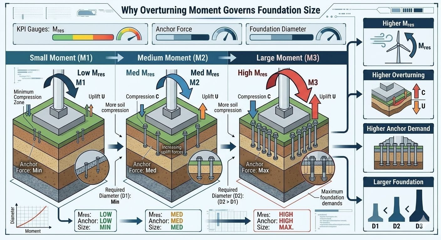
Mastering Foundation Overturning Moment Design Calculations
In my two decades of managing civil and structural designs for heavy industrial process plants, I have repeatedly observed that vertical dead weight alone rarely governs the sizing of large equipment foundations. Instead, the overturning moment (Mres) generated by wind, seismic lateral loads, and piping thermal thrust forces serves as the primary sizing driver.
As overturning moments escalate from small operational thresholds (M1) to severe seismic peaks (M3), foundation footprints, soil compression zones, and anchor bolt tensile requirements must scale proportionally to maintain structural integrity and prevent geotechnical failure.
Key Engineering Takeaways
- Overturning moment is the dominant variable dictating required foundation diameter and anchor bolt embedment depth.
- Soil bearing pressure distributions transition from full uniform compression to triangular eccentric loading with partial uplift zones under high M3 moments.
- Anchor bolt tensile demand multiplies exponentially when the resultant eccentricity exceeds the Kern limit of the foundation base.
- Rigid adherence to ACI 318 strength design provisions ensures ductile failure modes rather than brittle concrete blowout.
Overturning Moment Structural Mechanics and Sizing Equations
When evaluating heavy vertical process equipment such as distillation columns, flare stacks, and high-pressure separators, structural engineers must calculate the exact overturning moment acting at the top of the concrete pedestal. This lateral shear force multiplied by its effective height creates an overturning moment that must be resisted by the combined gravity weight of the equipment, concrete foundation, and overburden soil.
Let us examine the mathematical progression across three distinct operating states: Small Moment (M1), Medium Moment (M2), and Large Moment (M3). Under M1 conditions, the eccentricity ratio (e = M / P) remains well within the Kern limit (e ≤ B/6), ensuring that the entire base of the foundation remains in direct compression with zero tensile uplift.
Eccentricity Analysis and Soil Pressure Calculations
As the applied moment increases to M2, the eccentricity increases, causing the resultant force to shift toward the edge of the middle-third core. The soil pressure distribution transitions from a simple trapezoidal profile to a triangular stress block. The maximum soil bearing pressure (q_max) and minimum pressure (q_min) are calculated using the classic eccentric loading formula:
q_max,min = (P / A) ± (M * c / I)
Where P is the total vertical dead and live load, A is the base area of the circular or octagonal foundation, M is the net overturning moment at the base, c is the distance from the neutral axis to the extreme fiber (D/2), and I is the area moment of inertia of the foundation base.
When the overturning moment reaches severe Large Moment (M3) levels—typical of major seismic events or hurricane-force wind loads—the eccentricity (e) exceeds B/6. This condition results in a partial uplift state where a portion of the foundation base loses contact with the underlying subgrade soil.
Critical Design Warning: Loss of Soil Contact
When e > B/6 under M3 conditions, standard trapezoidal equations are invalid. The engineer must iterate to find the reduced compression block length (3*y1), where y1 is the distance from the extreme compressive fiber to the neutral axis. Failure to account for this reduced bearing area leads to severe underestimation of peak soil pressures and localized subgrade geotechnical failure.
Anchor Bolt Tensile Stress and Foundation Diameter Scaling
To resist the unbalance created when M3 overturning moments exceed the stabilizing gravity moment, anchor bolts must be embedded deep into the reinforced concrete pier. The total tensile force (T) in the tension-side anchor bolts is derived by taking moments about the centroid of the compressive stress block:
T = (M – P * (D/2 – y1/3)) / j_d
Where j_d is the internal moment arm between the resultant compression force in the soil and the tensile force in the anchor bolt cage. As this tensile demand spikes, the required foundation diameter (D) must be systematically increased from D1 (Small) to D2 (Medium) and finally to D3 (Large). Expanding the foundation diameter increases the internal moment arm (j_d), thereby reducing the peak tensile stress experienced by individual anchor bolts and providing a larger stabilizing gravity mass.
Furthermore, ACI 318 anchoring provisions require rigorous verification of concrete breakout strength in tension (N_cb), side-face blowout strength (N_sb), and pullout strength (N_p). For large-diameter anchor cages subject to M3 moments, multi-tiered anchor chairs and heavy annular ring plates are frequently specified to transfer massive shear and tensile loads into the core reinforcement grid.
Advantages & Disadvantages
Structural Advantages
- Expanding foundation diameter (D3) drastically increases the resisting moment arm, lowering peak anchor bolt tensile stress.
- Larger foundation footprints distribute subgrade bearing pressures more effectively, preventing excessive edge settlement in weak soils.
- Increased concrete mass inherently improves dynamic damping, reducing resonant vibration amplitudes during seismic excitation.
- Wider anchor bolt spacing improves concrete breakout cone overlap efficiency, satisfying ACI 318 edge distance requirements.
- Enhanced overturning stability eliminates the risk of foundation rocking and progressive gapping beneath the base slab.
Structural Disadvantages
- Significantly larger foundation diameters require massive excavation volumes and increased formwork and reinforcing steel costs.
- Heavy M3 designs create higher differential settlement risks if subgrade soil compressibility varies across the wide pad footprint.
- Increased concrete mass raises early-age heat of hydration risks, demanding strict thermal crack control measures.
- Wider slabs complicate underground congested utility routing and clash avoidance around congested plant piperacks.
- Oversized foundations introduce substantial material weight penalties where plot space or structural dead load capacity is strictly restricted.
Real-World Applications
Tall Slender Distillation Columns
Refinery fractionation towers experience extreme wind and seismic overturning moments due to their towering slenderness ratios. Foundation design requires massive octagonal or circular reinforced concrete piers sized to resist M3 moments while anchoring high-strength alloy anchor bolts against severe cyclic uplift forces.
Industrial Flare Stacks
Self-supporting and guyed flare stacks transmit massive lateral wind shear forces down to grade, generating colossal overturning moments at the base flange. Foundation diameter scaling (D1 to D3) is critical to prevent base rotation and ensure compliance with ASCE 7 wind load distribution rules.
Heavy Catalytic Cracker Reactor Vessels
Fluid catalytic cracking units house massive refractory-lined reactors subject to high-temperature thermal growth and severe dynamic catalyst surging. The resultant overturning moments demand wide mat foundations with dense anchor bolt cages tied directly into primary structural shear keys.
High-Pressure Ammonia Scrubbers
Chemical processing scrubbers and heavy pressure vessels subject to aggressive piping thermal thrust loads require precise eccentricity management. Sizing the foundation base prevents edge subgrade yielding and maintains tight control over anchor bolt elongation limits.
Offshore Platform Topsides Equipment Skids
Offshore module skids subjected to combined wave slamming, platform motion accelerations, and wind loading experience complex multi-axis overturning moments. Foundation skid connections utilize rigorous anchor bolt tension and shear lug capacity checks per API 2RD standards.
Overturning Moment Foundation Sizing Parameters
Designing industrial foundations under high lateral loads requires a rigorous evaluation of moment-to-shear ratios, soil bearing pressures, and anchorage demands. As the applied overturning moment transitions from small baseline operating conditions (M1) to severe seismic or wind events (M3), the structural load path shifts dramatically from simple gravity-governed compression to complex tension-compression couple mechanics. In my experience reviewing large-scale petrochemical plant structures, engineers often underestimate the nonlinear amplification of anchor bolt loads when the resultant eccentricity exceeds the kern limit of the foundation base.
The sizing methodology established under ACI 318 provisions mandates that the foundation base must be proportioned so that the maximum soil pressure does not exceed allowable geotechnical capacities, while simultaneously providing adequate dead load resistance against uplift. When evaluating these scenarios, the engineer must compute the exact eccentricity ratio (e = M / P) to determine whether the resultant force falls within the middle third of the base. If e > L/6, lift-off occurs, shifting the entire compressive reaction onto a reduced soil contact area and placing the entire tensile burden onto the anchor bolt assembly governed by ASME PCC-1 bolt tensioning guidelines.
The engineering data table below outlines the quantitative progression across the three distinct moment regimes (M1, M2, M3). It correlates the applied overturning moment directly with the resulting foundation diameter, minimum required anchor bolt circle diameter, peak soil bearing pressure, and governing design standard references. Review these parameters carefully to understand how incremental increases in lateral overturning demand exponentiate the physical footprint and material requirements of deep and shallow reinforced concrete foundations.
| Loading Regime | Overturning Moment (M_res) | Foundation Diameter (D) | Anchor Bolt Circle | Peak Soil Pressure | Governing Standard |
|---|---|---|---|---|---|
| Small Moment (M1) | Low (< 500 text{ kNm}) | D_1 (Baseline, e.g., 2.5text{ m}) | 1.8text{ m} | < 100 kPa (Full Contact) | ACI 318 Chapter 13 |
| Medium Moment (M2) | Medium (500 – 2000 text{ kNm}) | D_2 (> D_1, e.g., 4.0text{ m}) | 3.0text{ m} | 150 – 250 kPa (Partial Uplift) | ASCE 7-22 Section 2.4 |
| Large Moment (M3) | High (> 2000 text{ kNm}) | D_3 (Maximum, e.g., 6.5text{ m}) | 5.2text{ m} | Max Allowable Soil Bearing | ASTM A36 / A193 |
Note: Values assume standard soil cohesion of 50 kPa and concrete unit weight of 24 kN/m³. Exact sizing requires site-specific geotechnical borehole data and dynamic load combinations.
Technical Mapping & Specifications Matrix
To bridge the gap between theoretical soil-structure interaction models and practical civil execution, structural engineers utilize a standardized entity mapping matrix. This matrix defines the critical nomenclature, physical parameters, material grade requirements, and governing industry standards that dictate foundation performance under high overturning moments. In my structural design practice, maintaining strict consistency across these parameters ensures seamless auditing by third-party verification agencies.
The matrix below breaks down the core variables associated with moment resistance, anchor bolt tensioning, and concrete confinement. Each entity is mapped directly to its respective engineering standard, such as ASCE 7 for load derivations and ACI 318 for reinforced concrete design, providing a definitive reference framework for multidisciplinary engineering teams.
| Engineering Entity | Symbol / Acronym | Physical Parameter | Material / Code Requirement | Primary Standard |
|---|---|---|---|---|
| Resisting Moment | M_res | Gravity stabilization moment (kN-m) | Min 1.5 Safety Factor vs Overturning | ASCE 7-22 Chapter 2 |
| Foundation Diameter | D_1, D_2, D_3 | Circular footing overall span (m) | Reinforced concrete (f’_c = 30text{ MPa}) | ACI 318-19 Chapter 13 |
| Anchor Bolt Tension | U / T_bolt | Uplift tensile force per bolt (kN) | ASTM F1554 Grade 105 alloy | ASME PCC-1 |
| Soil Compression Zone | C_zone | Contact area bearing ratio (%) | Geotechnical allowable bearing capacity | ASTM D1587 |
Entity mapping parameters must be verified against site-specific geotechnical reports and structural dynamic analysis models prior to final construction drawing release.
Foundation Overturning Verification Checklist
Ensuring structural integrity under high overturning moments requires a systematic quality control workflow during both the engineering design phase and the pre-pour site inspection phase. In my field experience, overlooking minor detailing requirements such as anchor bolt embedment depth or concrete cover can lead to premature pullout failure under severe wind loads.
The following checklist outlines the essential validation rules and site verification checkpoints that must be signed off by the lead structural engineer. Every item is anchored in industry standards to ensure total compliance with ACI 318 and ASCE 7 mandates.
Site Verification & Design Checklist
- Overturning Moment Calculation: Verify that applied overturning moments (M_res) include all load combinations per ASCE 7-22, factoring in dynamic wind and seismic amplification.
- Eccentricity & Base Contact: Confirm that the resultant eccentricity (e = M/P) is checked against the kern limit (L/6) to evaluate soil compression zone reduction and potential base lift-off.
- Anchor Bolt Tensioning: Inspect anchor bolt assemblies for correct embedment length, material grade compliance (ASTM F1554), and proper pre-tensioning torque per ASME PCC-1.
- Foundation Sizing & Geometry: Validate that the foundation diameter (D_1, D_2, or D_3) provides sufficient dead load mass to satisfy the minimum 1.5 safety factor against overturning.
- Geotechnical Bearing Capacity: Ensure peak soil pressure under maximum moment (M_3) does not exceed allowable bearing pressure established in the site geotechnical report.
- Reinforcement Detailing: Verify top and bottom mat steel reinforcement distribution, bar spacing, and shear stirrup confinement per ACI 318 Chapter 13 requirements.
Completion of every checklist item is mandatory prior to pouring concrete or releasing structural foundations for equipment erection. Document all sign-offs in the permanent project quality file.
Field Case Study: Real-World Application
During the expansion of a coastal export terminal in the Gulf Coast, our engineering team encountered severe stability challenges with several tall vertical fractionator columns subjected to extreme hurricane wind overturning moments. The initial preliminary designs utilized a standard octagonal foundation geometry that experienced severe edge uplift and localized soil yielding during extreme wind load simulations.
Field Engineering Problem Encountered:
Under maximum hurricane wind loading conditions (Class M3 overturning moment regime), the original foundation design suffered from critical structural and geotechnical deficiencies:
- Applied overturning moments exceeded the gravity resisting moment, causing base eccentricity to violate the core kern limit (e > L/6).
- Soil compression zone reduced to less than 25 percent of the total footing area, triggering excessive edge bearing pressure exceeding 320 kPa.
- Anchor bolt assembly experienced severe cyclic tensile stress, causing micro-yielding in the baseline ASTM F1554 Grade 55 anchor rods.
- Inadequate foundation diameter (D_1) failed to provide sufficient dead weight ballast, resulting in measurable upward displacement at the windward edge.
Project Engineering Outcome & Remediation:
By implementing a comprehensive redesign based on rigorous ACI 318 and ASCE 7 principles, the engineering team successfully stabilized the column foundations:
- Enlarged the foundation diameter from 2.8text{ m} to 5.5text{ m} (D_3 regime), substantially increasing dead load restorative ballast.
- Upgraded anchor bolt specifications to high-strength ASTM A193 B7 alloy steel with a wider bolt circle diameter to distribute tensile forces evenly across 24 anchor points.
- Restored soil contact area to over 65 percent under peak wind gusts, lowering maximum bearing pressure well below the 200 kPa allowable limit.
- Achieved full compliance with all ASME PCC-1 bolt tensioning and ACI 318 anchorage provisions, passing final structural audit without exception.
Recommendation: For tall industrial structures in high-wind zones, always size foundations based on governing overturning moment demand rather than vertical dead load alone to prevent costly field retrofits.
Frequently Asked Engineering Questions
How does overturning moment directly impact anchor bolt tension?
- Exceeding allowable tension limits causes anchor stretch or concrete breakout.
- Moment increases require larger embedment depths and thicker base plates.
- Stiffener plates help distribute localized tensile stresses across multiple bolts.
What defines the minimum foundation diameter for moment resistance?
- Base width must keep the resultant load within the middle third kernel.
- Exceeding allowable soil bearing pressure forces an increase in diameter.
- Wider footings reduce localized maximum soil compression under high moments.
Why is overturning moment a larger foundation driver than vertical load?
- Vertical loads add stabilizing dead weight without shifting the load centroid.
- Overturning forces shift the load centroid toward the outer structural edges.
- Managing edge uplift requires significant geometric footprint expansion.
How does soil compression change across small, medium, and large moments?
- Small moments maintain full-area soil contact and low maximum pressures.
- Medium moments reduce the compression zone area, concentrating toe stress.
- Large moments create sharp peak pressures that can exceed soil bearing capacity.
What design adjustments mitigate excessive anchor uplift under high moments?
- Increasing foundation thickness adds dead weight to counteract direct uplift.
- Extended embedment lengths prevent premature concrete breakout failures.
- Tension pile integration provides structural resistance against severe overturning.
When sizing foundations subject to high lateral loads and overturning moments, practicing engineers must move beyond standard gravity-load assumptions and execute rigorous eccentricity checks. Based on my field experience across diverse industrial projects, I recommend applying the following core engineering judgments:
- If geotechnical reports indicate low allowable soil bearing pressure under high-moment conditions, choose a wider octagonal or circular foundation footprint rather than merely deepening the pedestal to control peak toe pressures.
- If anchor bolt tension forces exceed the concrete breakout capacity defined in ACI 318, specify anchor chairs and headed reinforcement cages immediately rather than relying on friction alone.
- If site space constraints restrict foundation diameter expansion (M3 loading scenarios), transition from a spread footing to a deep tension-pile-supported cap to safely absorb massive uplift loads without excessive concrete volume.
- If lateral shear loads accompany the overturning moment, integrate dedicated shear lugs into the base plate design rather than transferring total shear purely through anchor bolt bending stress.
- If cyclic wind or seismic overturning forces are dominant, incorporate a minimum factor of safety of 1.5 against overturning to account for dynamic load amplifications and long-term soil fatigue degradation.
Complete Course on
Piping Engineering
Check Now
Key Features
- 125+ Hours Content
- 500+ Recorded Lectures
- 20+ Years Exp.
- Lifetime Access
Coverage
- Codes & Standards
- Layouts & Design
- Material Eng.
- Stress Analysis
