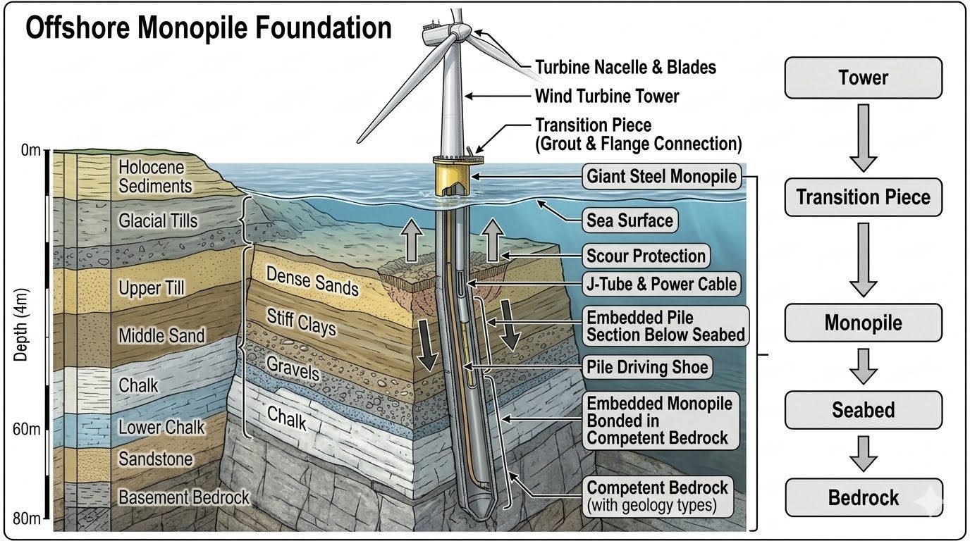
Offshore Monopile Foundation Design: Load Paths and Seabed Mechanics
In my two decades of managing major energy infrastructure projects, designing a resilient offshore monopile foundation requires an intimate understanding of complex marine load paths. The immense kinetic energy from the wind turbine nacelle and rotating blades translates downward through the wind turbine tower into the transition piece.
This connection point at the sea surface utilizes advanced grouting and high-strength flange assemblies to transfer multi-axial bending moments into a giant steel monopile. This massive tubular steel structure extends down through the water column, penetrating the dynamic seabed environment to secure structural stability.
Key Engineering Takeaways
- Precise load transfer from the turbine tower down through the transition piece and seabed.
- Geotechnical profiling of Holocene sediments, glacial tills, and chalk strata down to 80 meters.
- Rigorous fatigue and corrosion management under extreme cyclic wave and wind loading.
Structural Mechanics and Load Path Analysis in Monopile Design
When evaluating an offshore monopile foundation, I always begin by tracing the primary load path: Tower to Transition Piece to Monopile to Seabed to Bedrock. Every component along this chain must absorb immense dynamic fatigue stresses without exceeding allowable yield limits.
The wind turbine tower experiences continuous aerodynamic thrust forces. These forces create massive overturning moments that concentrate at the connection flange and the grouted annular space of the transition piece. I calculate these bending moments using integrated aero-hydro-servo-elastic modeling software compliant with DNV-ST-0126 guidelines.
Transition Piece Grout and Flange Mechanics
The transition piece acts as the vital mechanical bridge between the upper tower assembly and the subsea steel cylinder. Grout-filled annular spaces must withstand severe cyclic shear stresses induced by wave action and turbine yaw movements.
To prevent micro-cracking in the high-strength expansive grout, I specify strict limits on radial deformation and implement mechanical shear keys welded to the inner transition piece and outer monopile walls. These shear keys interlock the steel surfaces, transmitting axial loads and bending moments efficiently through friction and bearing resistance.
Critical Design Warning: Grout Fatigue Failure
Inadequate surface preparation or improper curing temperatures during offshore grouting can lead to premature debonding under cyclic shear stress. Always verify that the grout compressive strength exceeds 80 MPa at 28 days and maintain strict temperature monitoring within the annular space.
Seabed Geology and Soil-Structure Interaction
Below the water column, the giant steel monopile extends deep into the seabed. The surrounding seabed geology profile typically progresses through Holocene sediments, glacial tills, upper till, middle sand, chalk, lower chalk, and sandstone. Alternatively, profiles may feature dense sands, stiff clays, gravels, and chalk down to roughly 80 meters depth.
This complex stratigraphy dictates how deep the monopile must be driven to achieve adequate bearing and lateral resistance. I utilize finite element modeling based on P-Y curves (ASTM standards for soil testing) to analyze lateral soil-structure interaction. Soft Holocene surface layers offer minimal lateral resistance, requiring the pile to embed deeply into competent middle sands, glacial tills, or solid bedrock.
Scour Protection and Subsea Cable Routing
Erosion around the seabed interface remains a major threat to structural stability. I mandate engineered scour protection systems—typically consisting of graded rock placement or interlocking concrete mats—to prevent seabed lowering and subsequent loss of lateral pile fixity.
Furthermore, power cable routing requires integrated J-tubes welded along the outer or inner surface of the monopile. These J-tubes guide the subsea export cables safely from the seabed up into the transition piece, protecting electrical umbilicals from high-velocity tidal currents and vessel anchor strikes.
Pile Driving Dynamics and Bedrock Embedding
Driving a 10-meter diameter steel cylinder through dense sands and glacial tills into competent bedrock requires heavy hydraulic impact hammers. The pile driving shoe at the tip of the embedded pile section experiences extreme shock loads and compressive stress waves.
During driving operations, I closely monitor blow counts and stress wave propagation using wave equation analysis software (WEAP). If driving refusal occurs within hard chalk or sandstone strata without reaching target penetration, specialized drilling or socketing techniques must be deployed to ensure the pile achieves structural bonding and adequate ultimate capacity.
Advantages and Disadvantages of Monopile Foundations
Structural Advantages
- Proven installation methodology with high fabrication efficiency and rapid offshore deployment rates.
- Simplified structural geometry lacking complex subsea lattice nodes or welded brace intersections.
- Exceptional lateral load capacity derived from large-diameter steel bending stiffness in cohesive soils.
- Accommodates large modern multi-megawatt wind turbines with minimal seabed footprint disruption.
- Favorable fatigue performance when high-quality weld profiling and post-weld treatments are applied.
Structural Disadvantages
- Severe economic and logistical limitations in deep water environments exceeding 50 to 60 meters.
- Vulnerability to high-amplitude wave-induced scour requiring extensive preventative seabed armoring.
- Challenging pile driving refusal risks when encountering unforeseen boulders, hard rock, or cemented strata.
- High underwater noise emissions during heavy hammer driving requiring mandatory marine mammal mitigation.
- Complex residual stress management during thick-walled steel rolling and longitudinal seam welding.
Real-World Engineering Applications
Shallow Water North Sea Wind Farms
In typical North Sea deployment sites featuring dense sands and upper glacial tills in 30 meters of water, large-diameter monopiles serve as the baseline support structure. The high stiffness of the steel cylinder prevents excessive resonant vibration under severe wave climates.
Chalk Stratigraphy Penetration Projects
Projects situated over extensive upper and lower chalk formations require specialized drilling and driving sequences. Engineers utilize heavy hydraulic hammers combined with reverse circulation drilling inside the pile to penetrate cemented chalk layers and achieve target embedment depths.
Transition Piece Grouted Connections in Tidal Zones
High-current tidal straits utilize grouted transition piece connections to join the subsea monopile to the tower structure. The inclusion of internal mechanical shear keys guarantees secure load transfer under multi-directional hydrodynamic forces.
Deep Sand and Gravel Seabed Stabilization
Sites characterized by thick middle sand and gravel layers necessitate comprehensive scour protection engineering. Engineered rock dump matrices are installed immediately around the mudline to prevent localized liquefaction and scouring during extreme storms.
Offshore Monopile Structural and Geotechnical Design Parameters
Monopile structural engineering requires balancing extreme environmental hydrodynamic loading with complex geotechnical soil-structure interaction across multi-layered seabed profiles. In my professional experience designing offshore wind turbine support structures, selecting correct wall thicknesses and steel grades according to ISO 19902 and DNV-ST-0126 prevents premature fatigue failure and excessive lateral deflection at the mudline.
The table below compiles critical engineering parameters, standard dimensions, material grades, and governing design criteria utilized for large-diameter offshore wind turbine monopiles operating in water depths up to 50 meters.
| Design Parameter | Typical Range / Value | Governing Standard / Code | Engineering Significance |
|---|---|---|---|
| Monopile Diameter | 8.0 m to 11.5 m | DNV-ST-0126 | Controls overturning moment capacity and natural frequency of the turbine assembly. |
| Steel Yield Strength | S355 to S420 / S500 | EN 10025-4 | Determines resistance against extreme wave bending moments and cyclic fatigue. |
| Wall Thickness Range | 70 mm to 140 mm | ISO 19902 | Provides local shell buckling resistance and accommodates driving stresses during installation. |
| Embedment Depth | 30 m to 55 m below seabed | API RP 2GEO | Ensures adequate lateral bearing capacity using p-y curve soil reaction methods. |
| Grout Compressive Strength | Greater than 90 MPa at 28 days | DNV-OS-C502 | Transfers shear forces reliably between the transition piece and steel monopile. |
Table note: Values reflect modern multi-megawatt offshore wind turbine installations in North Sea environmental conditions.
Technical Mapping & Specifications Matrix
Modern offshore engineering projects rely heavily on standardized nomenclature and rigorous entity mapping to maintain structural integrity across multidisciplinary design teams. When evaluating complex geotechnical profiles spanning Holocene sediments down to competent chalk and sandstone, structural engineers must cross-reference mechanical material properties with environmental exposure categories defined in international codes.
The specification matrix below details the core structural entities, governing standards, acronyms, and operational verification parameters that form the backbone of offshore monopile foundation engineering.
| Entity / Component | Standard Reference | Key Physical Parameter | Design Verification Method |
|---|---|---|---|
| Transition Piece (TP) | DNV-ST-0126 | Grout annulus thickness and shear key geometry | Finite element analysis of contact pressure and slip failure. |
| Scour Protection System | BSEE / Coastal Guidelines | Rock grading size (typically 100-300 kg stones) | Physical hydraulic flume testing and hydrodynamic modeling. |
| J-Tube & Cable Routing | ISO 13628-5 | Bending radius and internal pull-in friction | Pull-in tension calculation and fatigue damage assessment. |
| Pile Driving Shoe | ASTM A572 Gr. 50 | Hardened steel tip reinforcement and bevel angle | Wave equation analysis program (GRLWEAP) impact simulation. |
Entity mapping note: All components must be coordinated through integrated 3D structural models to avoid clashes during offshore lifting and installation operations.
Offshore Monopile Site Verification Checklist
Rigorous site verification is mandatory before deploying massive steel monopiles into complex seabed stratigraphy consisting of Holocene sediments, glacial tills, and underlying chalk formations. In my engineering practice, skipping pre-installation geotechnical logging or weld inspections invariably leads to costly offshore delays or structural remediation offshore.
Use this comprehensive engineering checklist to validate site readiness, structural dimensions, and installation parameters in accordance with ISO 19902 and DNV-ST-0126 requirements.
Pre-Installation and Offshore Verification Steps
- Geotechnical Cone Penetration Testing (CPT): Verify soil shear strength profiles down to 80 meters depth across Holocene sediments, glacial tills, and upper/lower chalk layers.
- Seabed Obstruction & Bathymetry Scan: Perform high-resolution side-scan sonar surveys to clear boulder fields and confirm flat seabed landing zones for scour protection.
- Steel Plate Ultrasonic Testing (UT): Inspect all longitudinal and circumferential welds on the monopile cylinder per AWS D1.1 or ISO 17640 standards.
- Driving Shoe Structural Integrity: Verify bevel geometry and hardened steel hardness at the pile tip to withstand high-impact driving stresses in dense sand and chalk.
- Grout Annulus Quality Control: Check batch temperature, compressive strength test cubes (>90 MPa), and injection pressure sensors for the transition piece connection.
- J-Tube Alignment & Pressure Test: Conduct hydro-tests on internal cable routing conduits to ensure zero leakage and proper bend radii before turbine cabling.
Completing every item on this checklist ensures that the load path from the tower through the transition piece and monopile down to the competent bedrock remains fully compliant with structural safety margins throughout the 25-year design life.
Field Case Study: Real-World Application
During the installation of a 10-megawatt offshore wind farm in the North Sea, our engineering team encountered unexpected geotechnical refusal while driving a 9-meter diameter monopile through a dense glacial till layer overlying fractured lower chalk.
Field Problem Identified
Severe driving resistance occurred prematurely at 35 meters depth, falling 10 meters short of the required target embedment into competent sandstone bedrock.
- Hydraulic hammer blow counts exceeded 120 blows per 0.1 meters, triggering refusal criteria.
- Dynamic load testing indicated excessive compressive stress wave reflections building up in the steel wall.
- Unanticipated boulder clusters within the middle sand and upper till strata wedged against the pile exterior.
- Lateral bearing capacity calculations under preliminary depth failed to meet required safety factors for 50-year wave loads.
Engineering Solution and Outcome
Execution of an optimized internal soil-plug drilling procedure combined with specialized hydraulic jetting successfully bypassed the obstruction, achieving full embedment into competent bedrock.
- Deployed an internal reverse-circulation drill rig to remove 12 meters of dense plug material inside the monopile barrel.
- Resumed driving with a heavier hydraulic hammer, successfully advancing the pile tip 12 meters into competent sandstone.
- Conducted post-installation integrity testing confirming zero structural damage to the steel wall and driving shoe.
- Final resonance and fatigue analysis verified that the as-built foundation met all DNV-ST-0126 eigenfrequency criteria.
Recommendation for future projects: Always integrate high-resolution sub-bottom profiling with localized CPT testing every 50 meters across heterogeneous glacial till formations to anticipate hard driving layers and select appropriately sized hammers.
Frequently Asked Engineering Questions
What determines the required embedment depth for an offshore monopile foundation?
Embedment depth is governed by geotechnical profile mechanics and lateral load resistance requirements outlined in ISO 19900 standards:
- Stratigraphy traversal through Holocene sediments and glacial tills down to competent chalk or sandstone strata.
- Ultimate lateral bearing capacity calculations using p-y curve modeling for cyclic wind and wave loading.
- Overturning moment resistance provided by passive earth pressure in the lower foundation soils.
How does the transition piece manage loads between the tower and the monopile?
The transition piece transfers complex aerodynamic and hydrodynamic moments through a high-integrity connection system:
- High-strength structural bolted flanges or precision-engineered annular grout spaces bonding the steel sections.
- Load dissipation from the wind turbine tower down into the larger diameter primary steel cylinder.
- Microslip prevention and fatigue mitigation governed by DNV-ST-0126 design criteria.
What role do J-tubes play in offshore monopile structural design?
J-tubes serve as internal or external protective conduits for critical subsea power infrastructure:
- Safely housing inter-array high-voltage cables from the seabed up to the transition piece deck level.
- Shielding subsea cabling from hydrodynamic wave slamming, marine growth abrasion, and vessel impacts.
- Managing thermal expansion and contraction stresses via engineered sweep radii and clamp intervals.
Why is scour protection essential around the base of a monopile?
Scour protection prevents localized seabed erosion caused by amplified tidal and wave-induced flow velocities:
- Mitigating the loss of lateral soil confinement around the embedded section of the steel pile.
- Preventing critical reductions in natural frequency and long-term structural fatigue resistance.
- Utilizing graded rock armor layers or engineered geotextile mattresses in compliance with ABS marine standards.
How does seabed stratigraphy impact pile driving and driving shoe selection?
Stratigraphy variations from upper till to dense sands and chalk dictate installation energy and steel detailing:
- Equipping the pile tip with a hardened driving shoe to prevent localized buckling during hard driving.
- Managing high soil resistance to driving (SRD) in dense glacial tills and sandstone strata.
- Selecting hydraulic hammer energy ratings based on real-time soil resistance and refusal criteria.
Field Recommendation
Based on two decades of offshore installation experience, when designing and constructing large-diameter turbine foundations, I advise engineering teams to enforce the following operational judgments:
- If site cone penetration testing (CPT) reveals highly variable glacial till overlays above competent chalk, specify a reinforced, high-strength alloy driving shoe to prevent tip damage and structural buckling during hard driving operations.
- When designing the transition piece annular grout connection, always mandate acoustic emission monitoring during initial curing to detect micro-cracking and ensure compliance with DNV-ST-0126 fatigue thresholds under cyclic wind loading.
- Prioritize comprehensive multi-beam bathymetric surveys prior to scour protection installation; if local hydrodynamic velocity exceeds 1.5 meters per second, upgrade standard rock armor sizing to prevent premature displacement of the filter layer.
- For J-tube routing configurations, avoid tight bend radii near the transition piece entry point to eliminate stress concentration hotspots that could compromise internal high-voltage export cables during extreme wave slamming events.
Complete Course on
Piping Engineering
Check Now
Key Features
- 125+ Hours Content
- 500+ Recorded Lectures
- 20+ Years Exp.
- Lifetime Access
Coverage
- Codes & Standards
- Layouts & Design
- Material Eng.
- Stress Analysis
