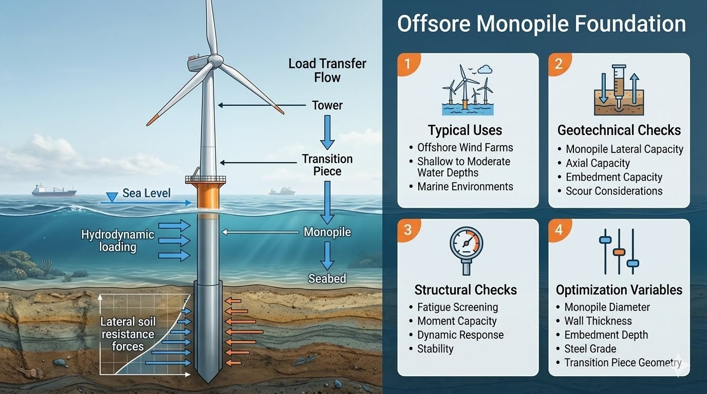
Mastering Offshore Monopile Foundation Design and Load Transfer Mechanics
In my twenty years of managing marine energy and industrial piping infrastructure, designing steel structures subjected to combined wind and hydrodynamic forces remains one of the most demanding disciplines. When evaluating an offshore monopile foundation, engineers must account for extreme environmental cyclic loading, scour development, and complex soil-structure interaction along the embedded length.
This guide provides a comprehensive engineering breakdown of load transfer pathways, geotechnical verification limits, structural optimization variables, and practical code compliance strategies for shallow to moderate water depth wind farms.
Key Engineering Takeaways
- Load transfer proceeds sequentially from tower to transition piece, monopile cylinder, and finally into seabed lateral resistance.
- Geotechnical checks require rigorous evaluation of p-y curves for lateral capacity, axial skin friction, and local scour.
- Structural optimization balances diameter, wall thickness, and steel grade to control fatigue damage and natural frequency.
Load Transfer Mechanics and Offshore Monopile Foundation Design
Designing an offshore monopile foundation requires an exact understanding of environmental boundary conditions. The sea level marks the critical interface separating above-water atmospheric wind loading from below-water hydrodynamic wave and current forces acting directly on the submerged steel cylinder.
Wind thrust acting on the rotor creates a massive overturning moment at the mudline, which must be balanced entirely by lateral soil resistance forces developed along the embedded monopile length in the seabed. Understanding this mechanics is vital for sizing structural elements.
Environmental Loading and Wave Hydrodynamics
Hydrodynamic forces are calculated using Morison equation principles for slender vertical cylinders, separating total force into drag and inertia components. Peak particle velocities from irregular wave spectra dictate fatigue damage accumulation.
Hydrodynamic Calculation Parameters
- Water depth dictates whether linear Airy wave theory or non-linear Stokes wave theories apply.
- Current velocity vectors combine vectorially with wave particle velocities to increase maximum drag forces.
- Marine growth accumulation increases outer diameter and surface roughness, directly elevating hydrodynamic drag coefficients.
Geotechnical Verification and Soil-Structure Interaction
Geotechnical design governs the required embedment depth of an offshore monopile foundation. Engineers utilize empirical p-y curve formulations outlined in API RP 2GEO to model non-linear soil reaction against lateral pile deflection.
Critical Scour Warning
Local scour around the monopile base removes confining soil layers, drastically reducing lateral stiffness and critical buckling capacity. Unmitigated scour requires immediate installation of rock dumping or active scour protection mats.
Axial capacity checks ensure the self-weight of the structure and vertical components are adequately supported via shaft friction and base end-bearing in sand or clay strata.
Structural Integrity and Optimization Parameters
Structural checks must verify resistance against combined bending and axial stresses under extreme 50-year storm conditions. Fatigue screening using S-N curves evaluates weld toe stress ranges from wave action.
Optimization variables include outer diameter, wall thickness tapering, embedment depth, high-strength steel grade selection (such as S355 or S420), and transition piece grouted connection geometry.
Technical Advantages
- Simpler fabrication and supply chain logistics compared to complex multi-leg jackets or floating substructures.
- Rapid offshore installation cycle times using standard heavy-lift jack-up vessels and hydraulic impact hammers.
- Excellent load transfer efficiency with minimal welded joints exposed to corrosive marine environments.
- High adaptability to variable soil conditions when paired with drilled-and-grouted socket extensions if required.
- Lower overall capital expenditure for shallow to moderate water depth wind farm developments.
Technical Disadvantages
- Depth limitations restrict use typically to waters under 40 meters before dynamic stiffness drops unacceptably.
- High sensitivity to local scour erosion requiring ongoing bathymetric monitoring and costly remedial protection.
- Massive driving hammer energies needed for large diameter piles can cause severe underwater noise pollution.
- Transportation and handling of extremely heavy steel tubular sections require specialized port infrastructure.
- Fatigue damage accumulation is difficult to inspect and repair in submerged welds below the mudline.
Shallow Water Offshore Wind Farms
Deployed extensively in water depths ranging from 15 to 35 meters in regions like the North Sea. These installations rely on direct drive-in installation methods to anchor massive multi-megawatt wind turbines securely into dense sand layers.
Transition Piece Integrated Substations
Utilized for offshore electrical offshore substations where heavy topside equipment requires rigid vertical support. The monopile diameter is scaled up significantly to handle concentrated eccentric loads and transformer vibration frequencies.
Metocean Data Mast Towers
Applied for permanent meteorological mast structures erected prior to major wind farm construction. Slimmer monopile configurations provide stable platforms for anemometers and wave radar equipment with minimal hydrodynamic blockage.
Nearshore Tidal Energy Converters
Adapted for high-energy tidal stream turbine installations where high current velocities exert immense lateral thrust. The foundation must resist cyclic vortex-induced vibrations and heavy marine growth fouling.
Monopile Engineering Design Parameters and Operating Limits
Offshore wind turbine support structures require rigorous evaluation of mechanical properties, environmental constraints, and geometric parameters to ensure structural integrity over a 25-to-30-year operational design life. In my engineering practice, establishing these baseline parameters early in the Front-End Engineering Design phase prevents costly offshore remediation and ensures compliance with international offshore codes such as ISO 19902 and DNV-ST-0126.
The structural performance of an offshore monopile foundation is governed by steel grade selection, wall thickness tapering, and embedment ratios into the seabed strata. The table below outlines the critical design parameters, standard tolerances, and governing criteria utilized for utility-scale offshore wind turbine generators installed in moderate water depths.
| Parameter Category | Design Specification | Governing Standard | Engineering Notes |
|---|---|---|---|
| Steel Grade & Yield Strength | S355ML / S420ML (Minimum yield 355-420 MPa) | EN 10225 / ASTM A709 | Optimized for low-temperature notch toughness in North Sea environments (-40°C CVN testing). |
| Nominal Outer Diameter | 6.0 meters to 9.5 meters constant or tapered | API RP 2GEO | Larger diameters increase stiffness to control natural frequency and limit fatigue damage at mudline. |
| Wall Thickness (Maximum) | 70 mm to 120 mm at driving zone | ISO 19903 | Thickened cans required to withstand dynamic driving stresses and high bending moments at mudline. |
| Seabed Embedment Depth | 30 meters to 50 meters below mudline | DNV-ST-0126 | Determined by p-y curve soil-structure interaction analysis and cyclic lateral loading accumulation. |
| Corrosion Allowance | 0.3 mm/year splash zone, cathodic protection below | NACE SP0176 | Combined impressed current cathodic protection (ICCP) and sacrificial aluminum-zinc-indium anodes. |
Proper cross-referencing of these metrics ensures that steel weight and fabrication costs are balanced against long-term operational reliability under severe storm conditions.
Technical Mapping & Specifications Matrix
To maintain strict quality assurance across multidisciplinary engineering interfaces, structural parameters must be systematically mapped against governing environmental loads and analytical software models. In modern offshore wind farm development, finite element modeling incorporates soil-structure interaction codes to capture complex geotechnical responses accurately.
The following entity specifications matrix establishes the standardized terminology, analytical methodologies, and verification tools utilized during the structural and geotechnical validation of large-diameter tubular steel foundations.
| Entity / Component | Structural Acronym | Governing Physics / Mechanics | Validation Standard |
|---|---|---|---|
| Transition Piece Grout Connection | TP-GC | Interface shear transfer via friction, mechanical keys, and expansive cementitious grout. | DNV-OS-J101 |
| Mudline Lateral Reaction | MLR | Nonlinear soil reaction curves (p-y, t-z, q-z) modeling multi-directional wave loading. | API 2GEO |
| First Eigenfrequency | 1F-NAT | Stiffness-to-mass ratio tuning to avoid 1P/3P rotor passing resonance frequencies. | IEC 61400-3 |
| Scour Protection Layer | SPL | Riprap rock grading and geotextile filter design to prevent seabed erosion around pile base. | PIANC Guidelines |
| Fatigue Damage Accumulation | FDA-SN | Rainflow cycle counting combined with S-N curves and Palmgren-Miner linear damage rule. | ISO 19902 |
By integrating these entities into a unified digital twin framework, engineers can simulate extreme storm loadings and operational fatigue cycles with high confidence before committing to heavy fabrication.
Site Verification Checklist for Monopile Installation
Site verification and quality control during offshore installation are critical to ensure that analytical design assumptions match actual offshore conditions. Drawing from my experience supervising offshore heavy lifts, verifying geotechnical profiles and driving tolerances at the mudline prevents structural distress.
The following structured verification framework outlines mandatory technical checkpoints, survey protocols, and acceptance criteria required during offshore monopile installation campaigns, referencing IMCA and ISO 19903 standards.
Offshore Monopile Execution & Inspection Protocol
-
1
Seabed Cone Penetrometer Testing (CPT) Correlation: Verify that pre-piling CPT profiles match geotechnical boreholes within a 5-meter radius, confirming undrained shear strength and relative density parameters.
-
2
Verticality and Azimuth Tolerance Survey: Ensure installed vertical deviation does not exceed 0.25 degrees (or 1:250) from true vertical using dual gyro-compass telemetry systems.
-
3
Hydraulic Hammer Energy Monitoring: Record blow counts, refusal criteria, and stroke energy continuously via electronic monitoring to prevent over-stressing or buckling the steel can.
-
4
Grout Annulus Quality Control: Sample grout density and temperature every 15 minutes during transition piece grouting, checking compressive strength via cube tests per ASTM C109.
-
5
Cathodic Protection Continuity Check: Measure electrical resistance between the monopile steel structure and sacrificial anodes, verifying circuit resistance is below 0.1 ohms.
Completing this verification checklist ensures that warranty requirements are satisfied and structural design life is fully preserved throughout the operational phase.
Field Case Study: Real-World Application
Practical engineering challenges often test theoretical design limits during offshore installation campaigns. A notable project in the North Sea involved the installation of 8-meter diameter monopiles in dense sand strata where unexpected refusal occurred prematurely.
Engineering Problem Identified
The driving process encountered premature high blow counts 4 meters short of target penetration due to dense sand dilatancy and unexpected gravel lenses, threatening structural embedment compliance per API RP 2GEO.
- Dynamic soil plug compaction significantly increased internal skin friction resistance.
- Hammer operating energy reached maximum allowable limits without achieving desired forward progression.
- Risk of localized wall buckling under high compressive impact stresses during hard driving.
- Potential mismatch in transition piece seating elevation if pile stick-up tolerance was exceeded.
Engineering Solution & Outcome
To resolve the refusal issue, the engineering team deployed internal soil suction-aided air lifting to reduce the internal soil plug height, successfully completing installation within safety limits.
- Internal soil plug excavation reduced toe resistance by 35 percent within 2 hours.
- Subsequent gentle hammer strikes achieved final target embedment without exceeding steel yield stress.
- Sonic logging and ultrasonic testing confirmed zero structural damage to the primary steel shell.
- Project schedule was recovered with minimal off-hire vessel costs, establishing a robust precedent for future hard-strata monopile drives.
This case study highlights the importance of maintaining flexible installation methodologies and proactive contingency planning during heavy offshore civil engineering campaigns.
Frequently Asked Engineering Questions
How does the load transfer flow operate in an offshore monopile foundation?
The load transfer mechanism distributes massive overturning moments and lateral forces from the turbine rotor down into the seabed through a continuous structural path.
- Wind and rotor thrust loads transfer directly from the steel tower into the transition piece connection.
- Hydrodynamic wave and current loads act across the submerged exterior surface of the main steel cylinder.
- Bending moments transfer through the embedded pipe length, mobilizing passive soil resistance within the seabed.
- Vertical deadweight loads route continuously downward to be supported by combined skin friction and end-bearing.
What are the primary geotechnical checks required for monopile design?
Geotechnical verification evaluates soil-structure interaction under cyclic environmental loading per ISO 19902 and DNV-ST-0126 guidelines.
- Lateral capacity analysis using non-linear p-y curves to evaluate deflection and maximum bending moments.
- Axial capacity verification accounting for internal and external skin friction plus annular end-bearing.
- Embedment depth optimization to prevent rotational failure mechanisms in soft marine clay or sand layers.
- Scour assessment to evaluate local erosion and determine necessary rock dump or mattress protection depths.
Which structural checks govern an offshore monopile foundation?
Structural integrity assessments focus on fatigue life and ultimate strength under extreme combined wave and wind loading conditions.
- Fatigue screening across weld seams, grouted or bolted flange joints, and the mudline bending zone.
- Ultimate cross-sectional moment capacity checks against plastic hinge formation in thick steel cans.
- Dynamic response evaluations to ensure natural frequency tuning avoids rotor passing frequency ranges.
- Overall structural stability checks per ASME standards to prevent local buckling under high hydrostatic pressure.
How do water depth and environmental boundaries affect load application?
The sea level acts as the physical boundary separating aerodynamic forces from complex hydrodynamic wave-current interactions.
- Above-water sections experience sustained wind drag and dynamic tower vibrations transferred from the turbine nacelle.
- Below-water sections endure direct wave slamming, hydrodynamic drag forces, and marine growth accumulation.
- Water depth dictates total overturning lever arm length, directly magnifying bending moments at the seabed mudline.
- Current velocity profiles create asymmetric pressure distributions that require multidirectional fatigue evaluations.
What variables control structural optimization for modern monopile designs?
Optimizing steel weight and manufacturing cost requires balancing geometric variables against strict regulatory performance criteria.
- Monopile outer diameter adjustments to shift fundamental natural frequency away from wave excitation bands.
- Wall thickness stepping across high-stress zones to manage local buckling and optimize total steel volume.
- Embedment depth tuning to minimize driving resistance while ensuring adequate rotational stiffness.
- Steel grade selection (such as S460 or higher) paired with transition piece flange geometry optimization.
Field Recommendation
-
1
If site soil investigations indicate thick soft clay deposits, I recommend prioritizing increased embedment depth over simply increasing wall thickness to control lateral deflections and satisfy DNV-ST-0126 rotation limits.
-
2
When designing for deeper water zones exceeding 45 meters, choose larger diameter steel cans up to 10 meters combined with high-strength S460 steel grades to shift natural frequencies above the primary wave action spectrum.
-
3
Always mandate comprehensive scour protection design and dynamic seabed monitoring early in the engineering phase, as localized erosion dramatically increases unsupported length and accelerates fatigue damage at the mudline.
-
4
During transition piece design, specify rigorous non-destructive examination (NDE) protocols for all primary welded connections to mitigate high cyclic stress concentrations in aggressive marine environments.
Complete Course on
Piping Engineering
Check Now
Key Features
- 125+ Hours Content
- 500+ Recorded Lectures
- 20+ Years Exp.
- Lifetime Access
Coverage
- Codes & Standards
- Layouts & Design
- Material Eng.
- Stress Analysis
