Table of Contents

Variable Spring Support Design Without Caesar II Hanger Auxiliary
In my 20+ years of piping stress analysis, I have seen a worrying trend: young engineers treating Caesar II as a black box. They input the geometry, click the “Hanger Auxiliary” button, and blindly accept whatever spring size the software spits out. But what happens when the software model has a hidden boundary condition error, or when you are at a remote project site without a software license and need to size a replacement spring immediately?
Relying solely on automated algorithms is a recipe for disaster. Understanding the fundamental mechanics of Variable Spring Support Design manually is not just an academic exercise; it is a safety-critical skill. When you design manually, you gain an intuitive grasp of how thermal displacement, spring rates, and piping weight interact. This first-principles approach allows you to spot software errors instantly and design robust, reliable support systems that protect sensitive equipment nozzles from catastrophic thermal loads.
Key Engineering Takeaways
- Master the core mathematical relationship between hot load, cold load, spring rate, and thermal travel.
- Learn how to enforce the 25% variability limit mandated by MSS SP-58 without software assistance.
- Acquire the skills to manually select spring sizes from manufacturer catalogs using raw structural data.
- Understand how to prevent spring bottoming out or complete load loss during extreme thermal cycles.
Complete Course on
Piping Engineering
Check Now
Key Features
- 125+ Hours Content
- 500+ Recorded Lectures
- 20+ Years Exp.
- Lifetime Access
Coverage
- Codes & Standards
- Layouts & Design
- Material Eng.
- Stress Analysis
Mastering Variable Spring Support Design Manually
To design a variable spring support manually, we must first understand the physics of a helical coil spring. Unlike rigid supports, a variable spring exerts a changing force on the pipe as the pipe moves vertically due to thermal expansion. The fundamental challenge is to select a spring that supports the pipe weight while keeping this force variation within acceptable limits.
The Governing Equations
The manual design process is governed by three primary variables: the Operating Load (also called the Hot Load), the Thermal Displacement, and the Spring Rate. Let us define these mathematically:
Once we have these values, we can calculate the Cold Load (P_cold), which is the force the spring exerts on the pipe when the system is cold (during installation or shutdown):
P_cold = P_op – (K * d) [For Upward Movement]
The 25% Variability Limit
The most critical design constraint in Variable Spring Support Design is the variability limit. As the pipe moves, the support force changes. If this change is too large, it can transfer massive, destructive loads to adjacent equipment nozzles or overstress the pipe itself. According to MSS SP-58 and ASME B31.3, the variability must not exceed 25% unless specifically approved.
The formula for calculating variability (V) is:
If your calculated variability exceeds 25%, you must select a spring with a lower spring rate (K). This is achieved by choosing a wider travel range series (e.g., moving from a short-range spring to a medium-range or double-range spring).
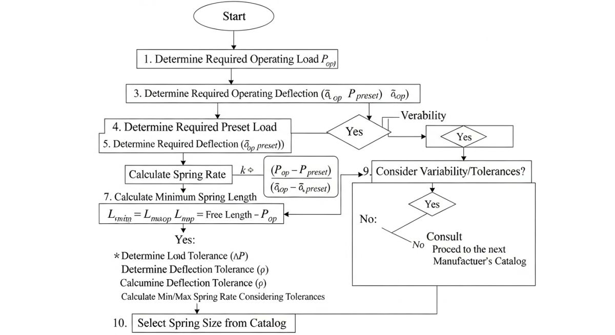
Step-by-Step Manual Selection Procedure
To perform this design manually, follow this rigorous engineering sequence:
- Determine the Operating Load (P_op): Run a deadweight analysis with a rigid support at the spring location to find the vertical support reaction.
- Determine the Thermal Movement (d): Calculate the vertical thermal expansion of the piping system at the support point.
- Select a Spring Series: Based on the thermal movement, select a preliminary spring series (e.g., Short, Medium, or Double Travel) from the manufacturer’s catalog.
- Find the Spring Size: Look up the catalog table for the selected series. Find the size where the Operating Load (P_op) falls near the middle of the working range. Note the corresponding Spring Rate (K).
- Calculate Cold Load and Variability: Use the formulas above to calculate P_cold and V. If V is greater than 25%, repeat the process with a softer spring series (lower K).
The table below provides typical spring rates and working ranges for standard variable spring hangers (equivalent to Grinnell Figure 268 / Lisega Type 21). These values are used to manually select the appropriate spring size based on your calculated operating load.
| Spring Size | Min Load (N) | Max Load (N) | Spring Rate (N/mm) | Max Travel (mm) |
|---|---|---|---|---|
| Size 1 | 120 | 480 | 7.2 | 50 |
| Size 2 | 240 | 960 | 14.4 | 50 |
| Size 3 | 480 | 1920 | 28.8 | 50 |
| Size 4 | 960 | 3840 | 57.6 | 50 |
| Size 5 | 1920 | 7680 | 115.2 | 50 |
This matrix maps the core technical entities, structural acronyms, and physical parameters required for manual spring design, cross-referenced with industry standards.
| Parameter / Entity | Acronym | Primary Unit | Standard Reference | Engineering Role |
|---|---|---|---|---|
| Operating Load | P_op | N or lbs | ASME B31.3 | Determines the baseline support force during hot operation. |
| Cold Preset Load | P_cold | N or lbs | MSS SP-58 | The load set at the factory to lock the spring during installation. |
| Spring Rate | K | N/mm or lb/in | MSS SP-58 | Defines the stiffness of the helical coil. |
| Support Variability | V | Percentage (%) | ASME B31.3 | Limits the load transfer to adjacent piping and equipment. |
Field Verification for Variable Spring Support Design
Even the most flawless manual design is useless if the field installation is executed poorly. In my experience, many piping failures occur because the construction crew failed to remove the travel stops or installed the spring upside down. Use this checklist on-site to verify every variable spring support before commissioning.
Pre-Commissioning Inspection Items
-
Verify Spring Tagging: Cross-reference the physical tag on the spring hanger with the piping isometric drawing and the manual design datasheet. Ensure the model, size, and serial number match.
-
Confirm Travel Stop Status: Ensure the factory-installed travel stops (locking pins or plates) are painted red and remain securely in place during hydrostatic testing.
-
Check Cold Preset Position: Verify that the load indicator pointer points exactly to the calculated cold load (P_cold) on the spring scale plate.
-
Inspect Angular Alignment: Ensure the hanger rod is vertical. The maximum allowable angular deviation is 4 degrees from the vertical axis to prevent binding.
-
Post-Startup Hot Verification: After the system reaches operating temperature, verify that the travel stops have been removed and the indicator has moved smoothly to the operating load (P_op) position without binding.
Field Case Study: Real-World Application
The Problem: Software Blindness Leads to Nozzle Overload
During the commissioning of a high-pressure steam line at a combined-cycle power plant, the steam turbine high-pressure nozzle experienced severe flange leakage. The stress analysis team had used Caesar II’s hanger auxiliary to design the spring support adjacent to the turbine.
Upon investigation, I discovered that a junior engineer had modeled the vertical thermal movement at the support as 12 mm upward, when in reality, due to a structural anchor displacement error, the pipe moved 18 mm downward. Because they relied entirely on the software’s automated selection, no one noticed that the selected spring (a short-travel model) completely bottomed out during operation, transferring a massive 45 kN rigid load directly onto the turbine nozzle.
The Outcome: Manual Recalculation and Resolution
I stepped in and bypassed the software entirely. Using the manual design steps outlined in this guide, I calculated the actual operating load (P_op = 18.5 kN) and the corrected thermal movement (d = -18 mm).
By manually calculating the variability for different spring rates, I determined that the original spring rate (K = 115 N/mm) resulted in a variability of over 110% under the corrected movement, which was a blatant violation of ASME B31.3. I selected a softer, double-travel spring with a spring rate of K = 28.8 N/mm. This reduced the variability to a safe 28% (approved by the turbine manufacturer) and completely eliminated the nozzle overload. The flange leakage stopped immediately upon startup.
My Direct Recommendation: Always perform a quick manual sanity check on your spring selections. If the software-selected spring rate seems unusually high for the thermal movement, calculate the variability manually. It takes less than five minutes and can save millions of dollars in equipment damage.
Frequently Asked Engineering Questions
Why is the variability limit set to 25% in ASME B31.3 and MSS SP-58?
What is the difference between a variable spring and a constant support?
How do I determine the operating load manually without a 3D model?
What happens if I install a spring support upside down?
When should travel stops be removed from a variable spring?
Can a variable spring support be used for horizontal thermal movement?
===

Complete Course on
Piping Engineering
Check Now
Key Features
- 125+ Hours Content
- 500+ Recorded Lectures
- 20+ Years Exp.
- Lifetime Access
Coverage
- Codes & Standards
- Layouts & Design
- Material Eng.
- Stress Analysis
📚 Recommended Resources: manual variable spring support design
Related posts:
![A mechanical sucker rod pumpjack operating in an oil field at sunset]()
What is Sucker Rod Pump System in Oil Production?
![Piping material engineer reviewing technical specifications on a tablet in an industrial plant.]()
How a Piping Material Engineer Drives Industrial Project Success
![Industrial refinery plant showing various types of static equipment]()
What is Static Equipment? Types and List of Static Equipments
![Side-by-side comparison of industrial process piping and power plant steam piping systems.]()
Differences Between ASME B31.3 and B31.1: B31.3 vs B31.1
![Large industrial steel storage tank under construction with cranes and scaffolding]()
Storage Tank Construction Method Statement: Step-by-Step Engineering Guide
![Cutaway diagram of a globe control valve highlighting the internal valve trim components]()
What is a Valve Trim? Types, Components, and Selection


