What are the Differences Between LNG and LPG?
Over my 20 years in piping engineering, I have stood on the freezing decks of LNG regasification terminals and walked the hot, dusty perimeters of LPG bullet storage yards. While both gases are hydrocarbons destined for the global energy sector, treating them as interchangeable is a recipe for catastrophic failure. The physical, chemical, and thermodynamic properties of these two fuels require entirely different engineering approaches.
In my experience, the most common mistakes occur during the early conceptual phase of dual-fuel terminal designs. Engineers often underestimate the extreme cryogenic demands of LNG or the high-pressure vapor characteristics of LPG. Understanding these differences is not just an academic exercise; it is a critical safety and operational requirement for any modern piping designer.
Key Engineering Takeaways
- Material Selection: LNG requires cryogenic-grade ASTM A312 TP316 stainless steel, while LPG utilizes standard ASTM A106 Grade B carbon steel.
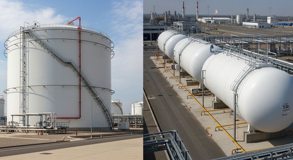
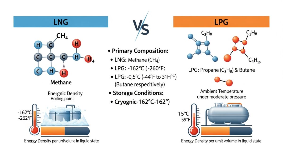
- Thermodynamic States: LNG is stored at atmospheric pressure and minus 162 degrees Celsius; LPG is stored at ambient temperature under pressures of 7 to 10 bar.
- Safety Codes: LNG facilities must comply with NFPA 59A, whereas LPG installations fall under NFPA 58.
- Vapor Density: LNG vapor (methane) is lighter than air at ambient temperatures and disperses upward, while LPG vapor is heavier than air and pools in low-lying areas.
Complete Course on
Piping Engineering
Check Now
Key Features
- 125+ Hours Content
- 500+ Recorded Lectures
- 20+ Years Exp.
- Lifetime Access
Coverage
- Codes & Standards
- Layouts & Design
- Material Eng.
- Stress Analysis
Understanding the Differences Between LNG and LPG in Piping Design
To design safe and efficient systems, we must look closely at the chemical compositions. LNG is primarily methane (CH4), which has a boiling point of minus 161.5 degrees Celsius at atmospheric pressure. LPG is a commercial mixture of propane (C3H8) and butane (C4H10), which liquefies at ambient temperatures under relatively low pressures (typically 7 to 10 bar gauge for propane at 37.8 degrees Celsius).
Cryogenic Piping Design for LNG
Because LNG operates at cryogenic temperatures, standard carbon steel cannot be used. Carbon steel undergoes a ductile-to-brittle transition at temperatures below minus 29 degrees Celsius, making it highly susceptible to catastrophic brittle fracture. Therefore, we specify austenitic stainless steels (such as ASTM A312 TP316 or TP304) or 9% nickel alloy steels, which retain their toughness and ductility at cryogenic temperatures.
Never allow carbon steel piping or supports to come into direct contact with LNG. A minor leak can cause localized cooling of adjacent carbon steel structures, leading to instantaneous brittle failure under normal operating loads. Always utilize cryogenic “cold shoes” made of high-density polyurethane or cellular glass to isolate the piping from structural steel.
Thermal Contraction Calculations for LNG
When an LNG pipeline is cooled from ambient installation temperature (say, 20 degrees Celsius) to its operating temperature of minus 162 degrees Celsius, it undergoes significant thermal contraction. Let us calculate the contraction of a 150-meter straight run of ASTM A312 TP316 stainless steel piping.
Formula: Delta L = L * alpha * Delta T
Where:
– L (Length of pipe) = 150 meters (150,000 mm)
– alpha (Mean coefficient of thermal expansion for TP316 from 20C to -162C) = 14.7 x 10^-6 m/m/K
– Delta T (Temperature difference) = -162C – 20C = -182 K
Calculation:
Delta L = 150,000 mm * (14.7 x 10^-6 / K) * (-182 K)
Delta L = 150,000 * 0.0000147 * -182
Delta L = -401.31 mm
A contraction of over 400 mm in a 150-meter run is massive. If this contraction is constrained, it will generate destructive tensile forces on the anchors and equipment nozzles. To mitigate this, we must design flexible piping layouts using expansion loops, offset bends, or specialized cryogenic bellows in accordance with ASME B31.3.
Pressurized Piping Design for LPG
LPG piping design focuses on pressure containment and vapor pressure management rather than cryogenic temperatures. Because LPG is stored as a liquid under its own vapor pressure, any drop in pressure or increase in temperature can cause the liquid to flash into gas. This vapor lock can ruin pumps and disrupt flow.
We typically specify ASTM A106 Grade B seamless carbon steel pipes with a minimum schedule of Schedule 40 or Schedule 80, depending on the pressure rating (usually ASME Class 150 or Class 300). Thermal expansion is still a factor due to solar radiation. For instance, an LPG line exposed to direct sunlight can reach temperatures of 60 degrees Celsius, requiring expansion loops to handle the positive expansion.
The following table outlines the critical physical and thermodynamic differences between LNG and LPG. These values are essential for sizing relief valves, calculating pipe wall thicknesses, and designing storage facilities.
| Property | Liquefied Natural Gas (LNG) | Liquefied Petroleum Gas (LPG) |
|---|---|---|
| Primary Chemical Component | Methane (CH4) > 90% | Propane (C3H8) and Butane (C4H10) mixtures |
| Boiling Point (at 1 atm) | Minus 161.5 degrees Celsius | Minus 42 degrees Celsius (Propane) |
| Storage State | Cryogenic liquid, atmospheric pressure | Pressurized liquid, ambient temperature |
| Liquid Density | 420 to 460 kg/m3 | 500 to 580 kg/m3 |
| Vapor Density (Relative to Air) | 0.55 (Lighter than air at ambient) | 1.5 to 2.0 (Heavier than air) |
| Liquid-to-Gas Expansion Ratio | 1 to 600 | 1 to 270 |
| Energy Density (Liquid Volumetric) | 22.2 MJ/liter | 25.3 to 27.7 MJ/liter |
This matrix maps the specific engineering standards, piping materials, and safety systems required for both LNG and LPG installations.
| Design Parameter | LNG Specification | LPG Specification |
|---|---|---|
| Primary Design Code | NFPA 59A / EN 1473 | NFPA 58 / API Std 2510 |
| Piping Material Specification | ASTM A312 TP316/316L, ASTM A333 Gr. 8 | ASTM A106 Gr. B, ASTM A333 Gr. 6 (for low ambient) |
| Valves Specification | BS 6364 (Cryogenic Valves), Extended Bonnet | API 6D, Standard Bonnet, Fire-safe design |
| Insulation System | Vacuum-jacketed or Cellular Glass with Vapor Barrier | Polyurethane Foam (PUF) or Uninsulated (with fireproofing) |
| Gasket Material | Spiral wound with Grafoil or PTFE filler | Spiral wound with Grafoil filler |
| Leak Detection Method | Fiber optic temperature sensing, IR gas detectors | Catalytic bead or IR point gas detectors at low levels |
Verifying the Differences Between LNG and LPG on Site
During the construction and commissioning phases, field engineers must maintain strict quality control. Mixing up materials or failing to verify installation tolerances can lead to catastrophic leaks during cool-down or pressurization.
Field Inspection Checklist
-
Positive Material Identification (PMI): Perform 100% PMI on all LNG piping components to verify they are cryogenic-grade stainless steel (TP316/316L) and not carbon steel.
-
Cold Shoe Support Alignment: Verify that LNG cold shoes are properly aligned and have sufficient clearance to allow for the calculated 400 mm of thermal contraction without falling off the support beams.
-
Vapor Barrier Integrity: Inspect the cellular glass insulation on LNG lines for a continuous, unbroken vapor barrier. Any moisture ingress will freeze, expand, and destroy the insulation.
-
LPG Relief Valve Settings: Ensure that LPG hydrostatic relief valves are installed on any piping section that can be isolated by valves. This prevents overpressure from solar heating of trapped liquid.
-
Gas Detector Placement: Verify that LPG gas detectors are placed close to the ground (within 0.5 meters) because LPG vapor is heavier than air. Conversely, LNG detectors should be placed high in enclosed areas.
Field Case Study: Real-World Application
The Problem: Cryogenic Backflow into Carbon Steel
During a fast-track dual-fuel terminal expansion in Southeast Asia, a utility line designed for LPG (carbon steel ASTM A106 Grade B) was accidentally exposed to cryogenic LNG temperatures. A leaking isolation valve allowed LNG to backflow into the pressurized LPG line. Within minutes, the carbon steel pipe temperature dropped to minus 80 degrees Celsius, well below its ductile-to-brittle transition temperature. The internal pressure of 8 bar gauge caused a sudden, catastrophic brittle rupture of the pipe, releasing a large vapor cloud.
The Outcome: Redesign and Safety Interlocks
As the lead consulting engineer brought in to investigate, I immediately ordered a complete redesign of the interface. We replaced the single isolation valve with a Double Block and Bleed (DBB) valve arrangement equipped with an automated bleed to atmosphere. We also replaced the first 15 meters of the LPG carbon steel line with ASTM A312 TP316 stainless steel to act as a thermal buffer zone. Finally, we installed skin temperature transmitters on the piping with an automated ESD (Emergency Shutdown) interlock to close the LNG source if temperatures dropped below minus 20 degrees Celsius.
This incident highlights why we must never rely solely on manual valves to separate cryogenic and non-cryogenic systems. The thermodynamic differences between LNG and LPG require robust physical separation and smart instrumentation.
Frequently Asked Engineering Questions
Why can’t we use LPG storage tanks for LNG?
What is the difference in vapor dispersion behavior between LNG and LPG?
Which gas has a higher energy density?
What are the key differences in valve design for LNG and LPG?
How do hydrostatic testing requirements differ?
Which standards govern the spacing of storage vessels?
===

Related posts:
![Aerial view of a BESS facility construction site showing earthwork grading, soil compaction, and site preparation for battery storage containers.]()
Earthwork Optimization for BESS Facilities: A Civil Engineering Guide
![Isometric view of a BESS site grading design showing battery containers, access roads, and perimeter drainage systems on a leveled site.]()
Essential Grading Design for BESS Sites: Engineering and Site Optimization
![Modern BESS facility site layout showing elevated concrete foundations and perimeter flood protection barriers for industrial safety.]()
Flood Protection for BESS Facilities: Engineering Design and Mitigation
![Utility-scale BESS container units installed on reinforced concrete slab foundations at a solar-plus-storage project site.]()
Essential Foundation Requirements for BESS Containers: A Technical Design Guide
![Aerial view of a utility-scale BESS facility showing containerized battery units, power conversion systems, and grid interconnection infrastructure in a flat, accessible site.]()
Strategic Site Selection Criteria for BESS Facilities Engineering Design
![Cross-section view of green hydrogen plant foundations showing soil strata and groundwater interaction for geotechnical risk assessment.]()
Managing Geotechnical Risks in Green Hydrogen Infrastructure Projects