What is Liquefied Petroleum Gas or LPG?
In my 20-plus years of designing piping systems and refinery storage facilities, I have seen how Liquefied Petroleum Gas (LPG) behaves under varying thermal and pressure conditions. It is not just a simple fuel; it is a highly volatile, pressurized liquid that demands precise thermodynamic calculations and strict adherence to safety codes. When you are dealing with a substance that expands 270 times its liquid volume when vaporized, there is zero margin for error.
In this guide, I will break down the chemical composition, physical properties, and engineering design parameters that govern safe LPG handling. Whether you are designing a bulk terminal or specifying piping materials, understanding these fundamentals is critical to preventing catastrophic system failures.
Key Engineering Takeaways:
- Understand the phase-change behavior of propane-butane mixtures under varying ambient temperatures.
- Master the design pressure requirements for storage vessels according to ASME Section VIII Division 1.
- Implement robust safety relief systems to prevent Boiling Liquid Expanding Vapor Explosions (BLEVE).
Complete Course on
Piping Engineering
Check Now
Key Features
- 125+ Hours Content
- 500+ Recorded Lectures
- 20+ Years Exp.
- Lifetime Access
Coverage
- Codes & Standards
- Layouts & Design
- Material Eng.
- Stress Analysis
Understanding the Thermodynamics of Liquefied Petroleum Gas
LPG is primarily sourced from natural gas processing and crude oil refining. The exact ratio of propane to butane is adjusted seasonally and geographically to optimize vapor pressure. For instance, in colder climates, a higher propane concentration is required to maintain adequate vapor pressure at low temperatures. Conversely, in warmer regions, butane content is increased to prevent excessive pressure build-up inside storage vessels.
Let us look at the fundamental physical properties of the two primary components:
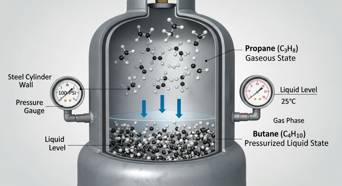
- Propane (C3H8): Boiling point of -42 degrees Celsius (-44 degrees Fahrenheit) at atmospheric pressure. Vapor pressure at 37.8 degrees Celsius (100 degrees Fahrenheit) is approximately 1.3 MPa (190 psig).
- Butane (C4H10): Boiling point of -0.5 degrees Celsius (31 degrees Fahrenheit) at atmospheric pressure. Vapor pressure at 37.8 degrees Celsius (100 degrees Fahrenheit) is approximately 0.36 MPa (52 psig).
To calculate the vapor pressure of an LPG mixture, we apply Raoult’s Law for ideal mixtures, though real-world applications require the Peng-Robinson equation of state for high-accuracy phase-equilibrium modeling. The simplified mixture vapor pressure (P_mix) can be estimated as:
Where x represents the liquid mole fraction of each component, and P represents the pure component vapor pressure at the operating temperature.
When designing piping systems under ASME B31.3, we must account for the minimum design metal temperature (MDMT). If an LPG system undergoes rapid depressurization (auto-refrigeration), the temperature can drop to -42 degrees Celsius. This requires the use of impact-tested materials, such as ASTM A333 Grade 6 carbon steel, rather than standard ASTM A106 Grade B, to prevent brittle fracture.
CRITICAL SAFETY WARNING: Liquid Thermal Expansion
LPG has an extremely high coefficient of volumetric expansion. If liquid LPG is trapped between two closed valves without a thermal relief valve (TRV), a temperature rise of just 1 degree Celsius can increase the internal pressure by approximately 5 to 6 MPa (725 to 870 psi). This will inevitably lead to catastrophic piping rupture. Always install thermal relief valves set to discharge back to the storage vessel or a safe disposal system.
| Property | Propane (C3H8) | Butane (C4H10) | Reference Standard |
|---|---|---|---|
| Boiling Point (at 1 atm) | -42.1 °C (-43.8 °F) | -0.5 °C (31.1 °F) | GPA Standard 2145 |
| Vapor Pressure (at 37.8 °C / 100 °F) | 1.31 MPa (190 psig) | 0.36 MPa (51.6 psig) | ASTM D1267 |
| Liquid Density (at 15 °C) | 506 kg/m³ | 584 kg/m³ | ASTM D1657 |
| Flammability Limits in Air | 2.1% to 9.5% (Vol) | 1.8% to 8.4% (Vol) | NFPA 325 |
| Latent Heat of Vaporization (at boiling) | 426 kJ/kg | 385 kJ/kg | ASHRAE Handbook |
| System Component | Primary Standard | Key Design Parameter | Material Specification |
|---|---|---|---|
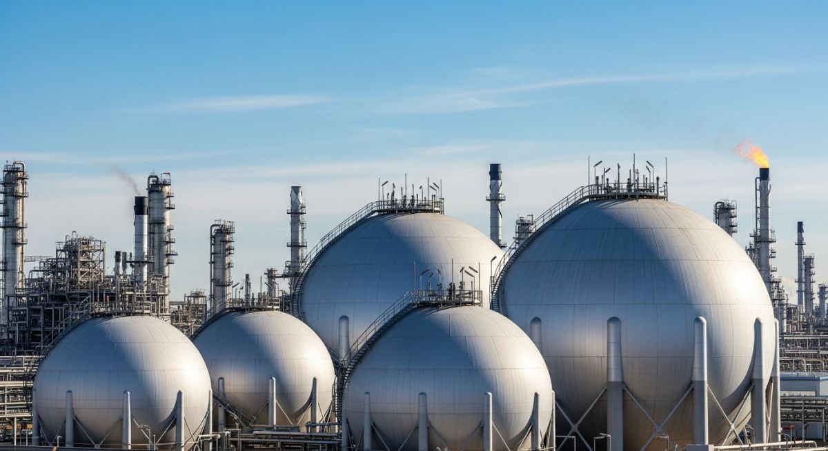
| Storage Vessels (Bullet/Sphere) | ASME BPVC Sec VIII Div 1 | Design Pressure: Min 1.72 MPa (250 psig) | ASTM A516 Grade 70 (Normalized) |
| Process Piping | ASME B31.3 | Flange Rating: ASME Class 300 minimum | ASTM A333 Grade 6 / ASTM A105 |
| Safety Relief Valves | API Standard 520 / 526 | Fire sizing scenario (Wetted surface area) | Stainless Steel Trim (316 SS) |
| System Installation | NFPA 58 | Separation distances & vapor barriers | N/A (Spatial Layout) |
Site Verification Checklist for Liquefied Petroleum Gas Systems
Before introducing liquid LPG into any newly constructed or modified piping system, I always insist on a rigorous physical walkdown. The checklist below represents the minimum verification steps required to ensure the system is safe for commissioning.
Pre-Commissioning Field Checklist:
-
Hydrostatic Testing: Verify that hydrostatic testing has been completed at 1.5 times the design pressure in accordance with ASME B31.3, and that the system has been completely dried with nitrogen to a dew point of -40 degrees Celsius. -
Electrical Grounding: Confirm that all piping flanges are bonded and the storage vessel grounding resistance is less than 10 Ohms to prevent static electricity accumulation. -
Thermal Relief Valves (TRVs): Verify that TRVs are installed on all liquid-trappable segments and that their discharge lines are routed back to the vapor space of the storage vessel. -
Emergency Shutdown Valves (ESVs): Test the fail-safe closure of all pneumatic and hydraulic ESVs. Ensure they close fully within 5 seconds of activation. -
Gas Detection: Confirm that catalytic or infrared combustible gas detectors are calibrated and positioned at low points, as LPG vapors are heavier than air and will pool in low-lying areas.
Field Case Study: Real-World Application
The Problem: Vapor Lock and Cavitation in LPG Transfer Pumps
At a bulk LPG terminal in the Middle East, a set of multi-stage centrifugal transfer pumps experienced severe cavitation and mechanical seal failures during summer operations when ambient temperatures reached 48 degrees Celsius. The system was transferring a 60/40 propane/butane mix from mounded storage vessels to road tankers. The high ambient heat caused the LPG inside the suction piping to flash into vapor, resulting in vapor lock. The Net Positive Suction Head Available (NPSHa) dropped below the Net Positive Suction Head Required (NPSHr), causing immediate pump degradation.
The Outcome: Hydraulic Optimization and Vapor Return Line Redesign
As the lead piping consultant, I redesigned the suction piping configuration to minimize friction losses. We increased the suction line size from 4 inches to 6 inches, reducing the fluid velocity and pressure drop. Additionally, we installed a dedicated vapor-equalizing line between the road tanker and the storage vessel to balance the pressures during transfer. Insulation and reflective white coatings were applied to all exposed suction piping to minimize solar heat gain. These modifications increased the NPSHa by 1.2 meters, completely eliminating cavitation and extending the mechanical seal life from 3 weeks to over 3 years.
Direct Recommendation: When designing LPG pumping systems, always calculate NPSHa under the worst-case summer ambient temperatures. Never rely on nominal fluid properties; use the maximum vapor pressure of the specific hydrocarbon blend to ensure the liquid remains subcooled throughout the suction path.
Frequently Asked Engineering Questions
What is the difference between LPG and LNG?
Why is an odorant added to LPG, and what chemical is used?
What are the design pressure requirements for LPG storage vessels?
How does temperature affect the liquid level in an LPG tank?
What is a BLEVE, and how is it prevented in LPG installations?
Which piping materials are approved for LPG service?

📚 Recommended Resources: Liquefied Petroleum Gas
Read these Guides
🎓 Advanced Training
🎥 Watch Tutorials

Related posts:
![Aerial view of a BESS facility construction site showing earthwork grading, soil compaction, and site preparation for battery storage containers.]()
Earthwork Optimization for BESS Facilities: A Civil Engineering Guide
![Isometric view of a BESS site grading design showing battery containers, access roads, and perimeter drainage systems on a leveled site.]()
Essential Grading Design for BESS Sites: Engineering and Site Optimization
![Modern BESS facility site layout showing elevated concrete foundations and perimeter flood protection barriers for industrial safety.]()
Flood Protection for BESS Facilities: Engineering Design and Mitigation
![Utility-scale BESS container units installed on reinforced concrete slab foundations at a solar-plus-storage project site.]()
Essential Foundation Requirements for BESS Containers: A Technical Design Guide
![Aerial view of a utility-scale BESS facility showing containerized battery units, power conversion systems, and grid interconnection infrastructure in a flat, accessible site.]()
Strategic Site Selection Criteria for BESS Facilities Engineering Design
![Cross-section view of green hydrogen plant foundations showing soil strata and groundwater interaction for geotechnical risk assessment.]()
Managing Geotechnical Risks in Green Hydrogen Infrastructure Projects