What is Process Control? Its Importance and Working Principle

Imagine standing in a high-pressure refinery where a mere 2-degree temperature spike could trigger a catastrophic runaway reaction or ruin a multi-million dollar batch of specialty chemicals. You are not just fighting physics; you are fighting disturbances like ambient weather changes and fluctuating feed rates. This article provides the technical blueprint to mastering Process Control, moving beyond basic definitions to show you how to architect loops that maintain rock-solid stability under pressure.
Key Engineering Takeaways
- Understanding the critical transition from Open-loop to Closed-loop architectures.
- Mastering the mathematical relationship between the Set Point and the Manipulated Variable.
- Strategies for achieving Disturbance Rejection using PID algorithms and Feed-forward logic.
What is Process Control?
Process Control is the engineering discipline that uses industrial control systems to maintain the output of a specific process within a desired range. By continuously measuring a Controlled Variable and adjusting a Manipulated Variable, the system counteracts disturbances to ensure operational safety, product consistency, and efficiency.
“In my 20 years of plant commissioning, I’ve seen that 90% of loop failures aren’t caused by bad software, but by poor understanding of the Final Control Element dynamics. Process Control is as much about the mechanical response of a valve as it is about the code in the PLC.”
– Atul Singla, Founder of EPCLand
Table of Contents
Complete Course on
Piping Engineering
Check Now
Key Features
- 125+ Hours Content
- 500+ Recorded Lectures
- 20+ Years Exp.
- Lifetime Access
Coverage
- Codes & Standards
- Layouts & Design
- Material Eng.
- Stress Analysis
Process Control Engineering Quiz
Question 1 of 5In a standard feedback loop, which component is responsible for comparing the Set Point with the Process Variable?
What is Process Control?
In industrial environments, Process Control refers to the automated methods used to maintain the output of a specific process within a desired range. Whether it is the temperature of a chemical reactor, the pressure in a steam pipe, or the flow rate of fuel to a turbine, Process Control ensures that these variables remain steady despite external influences. By utilizing a mix of hardware (sensors, controllers, and valves) and software (algorithms like PID), engineers can achieve high levels of safety and efficiency that would be impossible through manual operation alone.
Why Process Control is Essential in Modern Industry?
The necessity of robust Process Control cannot be overstated. Without it, industrial plants would face significant risks, including equipment damage, environmental hazards, and inconsistent product quality. For example, in pharmaceutical manufacturing, a slight deviation in pH levels—a key Process Control variable—can render an entire batch of medicine useless. Furthermore, modern Process Control systems optimize energy consumption, reducing the carbon footprint of heavy industries by ensuring that furnaces and boilers operate at peak thermal efficiency.
Understanding the Process Control System Architecture
Every Process Control system is built upon a standard architecture consisting of three primary stages: measurement, decision-making, and action. First, a sensor measures the current state. Second, the controller evaluates this data against a set target. Finally, the controller sends a signal to an actuator to adjust the process. This structural integrity is governed by international standards such as ISA-5.1, which provides the framework for instrumentation symbols and identification.
Defining the Error Signal in Process Control
The “Error” is the heartbeat of any Process Control loop. Mathematically, it is the difference between the Set Point (SP)—what you want—and the Process Variable (PV)—what you currently have. In Process Control, the goal of the controller is to drive this error signal to zero. If the error is positive, the controller increases its output; if negative, it decreases it. Understanding the magnitude and duration of this error is critical for tuning stable loops.
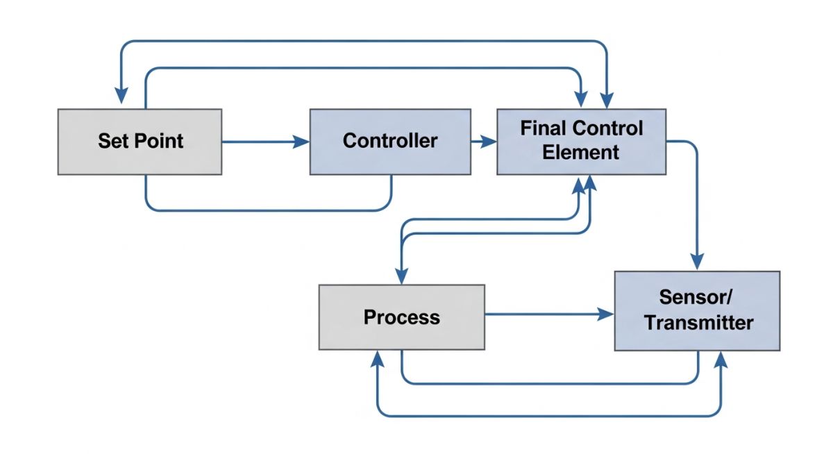
How to Read a Process Control Block Diagram
A Process Control block diagram is a visual shorthand used by engineers to represent the signal flow between components. Each block represents a mathematical transfer function. The circles, or “summing junctions,” represent the points where the feedback signal is subtracted from the set point to create the error. Mastering these diagrams is the first step in performing a rigorous Process Control stability analysis, often involving Laplace transforms to predict how the system will react to sudden changes.
Closed-loop vs. Open-loop Process Control
The fundamental distinction in Process Control is between open and closed loops. An Open-loop system acts without checking the results (like a toaster running for a set time regardless of how burnt the bread is). In contrast, a Closed-loop Process Control system uses a feedback path. It constantly “closes the loop” by measuring the output and feeding that information back to the controller. This makes closed-loop systems far superior for handling unpredictable disturbances in industrial settings.
Identifying the Controlled Variable in a Process Control Loop
The Controlled Variable (also known as the Process Variable) is the specific parameter that you are trying to maintain at a constant level. In a home heating system, the temperature of the air is the controlled variable. In an industrial Process Control scenario, identifying the correct variable is essential; for instance, in a distillation column, you might control the top tray temperature as a proxy for product purity. Selection of the wrong variable can lead to sluggish Process Control and poor economic performance.
The Role of the Controller in Process Control
The controller acts as the central nervous system of any Process Control strategy. It receives the error signal and calculates the required output to the final control element using specific algorithms. In high-stakes industrial environments, these controllers often follow ASME and ISA standards to ensure reliability and interoperability. The mathematical sophistication of the controller—ranging from simple gain adjustments to complex derivative filters—determines the speed and stability of the entire Process Control loop.
Achieving Disturbance Rejection in Process Control
Disturbance rejection is the primary metric for Process Control performance. A disturbance is any unplanned change in the process inputs—such as a sudden drop in ambient temperature or a spike in feed pressure—that forces the Controlled Variable away from the Set Point. Effective Process Control design ensures the system can suppress these “noise” factors without overshooting or causing oscillations. High-performance loops utilize high-speed sampling to detect disturbances before they propagate through the entire system.
Managing the Manipulated Variable for Effective Process Control
The Manipulated Variable (MV) is the factor that the controller adjusts to exert influence over the process. For example, in a temperature-controlled tank, the flow rate of steam is the MV. Engineering a robust Process Control loop requires understanding the physical limits of the MV; a valve can only open 100%, and a pump has a maximum RPM. When the Process Control system demands a change beyond these physical limits, it enters a state called “Saturation,” which can lead to “Reset Windup” and system instability.
Comparison of Process Control Strategies
| Control Strategy | Response Type | Best For… | Limitation |
|---|---|---|---|
| On-Off | Reactive/Binary | Non-critical HVAC | High Wear on Actuators |
| Proportional (P) | Continuous | Simple Level Loops | Inherent Offset |
| PI Control | Eliminates Offset | Flow/Pressure Loops | Can cause overshoot |
| Full PID | Predictive/Steady | Temperature Control | Complex to tune |
Implementing PI and PID Algorithms for Advanced Process Control
Most industrial Process Control applications rely on the PID (Proportional-Integral-Derivative) algorithm. Proportional action provides an immediate response to the current error. Integral action (I) integrates the error over time to eliminate the steady-state “offset” that plagues simple P-controllers. Derivative action (D) looks at the rate of change, effectively predicting where the error will be in the future to dampen the system’s response. Proper tuning of these three parameters—Gain, Reset, and Rate—is the hallmark of an expert Process Control engineer.
Feed-Forward Control vs. Feedback Process Control
While feedback Process Control is the standard, it is fundamentally “reactive”—it waits for an error to occur before taking action. Feed-Forward Control is “proactive.” It measures incoming disturbances (like the temperature of the raw material entering a heater) and adjusts the Manipulated Variable before the output is ever affected. In modern automation, engineers often combine both methods into a “Feed-forward plus Feedback” architecture to achieve near-perfect Process Control stability in highly volatile environments.
🧮 Proportional (P) Controller Error Calculator
Calculate the Controller Output and resulting Error based on your Gain (Kp) settings. This tool helps visualize why Proportional action alone often results in a steady-state offset in Process Control.
Case Study: Solving Steam Pressure Instability in a 2026 Power Plant
The Challenge: Severe Pressure Surges
A mid-sized thermal power plant faced recurring turbine trips due to erratic steam header pressure. Traditional Process Control feedback loops were too slow to react to sudden load changes from the grid, causing the steam pressure to swing by ±15% of the Set Point.
The existing Proportional-Integral (PI) controller was fighting a losing battle against downstream demand spikes (disturbances) that occurred faster than the sensor could report the pressure drop.
The Engineering Solution
- Integrated Feed-forward Control logic to monitor turbine load demand directly.
- Replaced the aging Final Control Element with a high-speed pneumatic globe valve.
- Tuned a PID Algorithm with a strong derivative component to “predict” pressure crashes.
The 2026 Result
By combining proactive feed-forward signals with reactive feedback, the Process Control system reduced pressure deviation to less than 1.5%. This optimization resulted in a 4% increase in overall fuel efficiency and eliminated unscheduled turbine shutdowns.
Expert Insights: Lessons from 20 years in the field
-
Prioritize Loop Integrity: Before you touch the PID tuning, verify the mechanical health of your Final Control Element. No amount of advanced Process Control logic can compensate for a control valve with high “stiction” or a sensor with excessive signal noise.
-
Stability Over Speed: In industrial Process Control, an overdamped response is almost always preferable to an underdamped one. While rapid recovery is tempting, excessive oscillation causes mechanical fatigue and thermal stress on downstream equipment.
-
Documentation is Survival: Always adhere to ISA-5.1 standards for tagging and P&ID symbols. In a critical plant upset, the speed at which a technician can identify the Controlled Variable on a drawing determines the speed of recovery.
