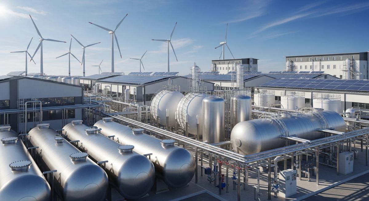
Hydrogen Storage Technologies: A Comprehensive Engineering and Selection Guide
In my 20 years of designing piping systems and high-pressure storage facilities, I have seen many engineers treat hydrogen like standard natural gas. That is a recipe for disaster. Hydrogen is a unique, highly challenging molecule. It is the smallest element in the universe, meaning it leaks through the tiniest microscopic pathways. It has a wide flammability range of 4 percent to 75 percent in air, and it actively degrades high-strength steels through hydrogen embrittlement.
As we transition toward clean energy, selecting and designing the right storage system is not just a matter of cost; it is a matter of safety, efficiency, and long-term mechanical integrity. In this guide, I will share my hands-on field experience and the exact engineering calculations you need to evaluate and implement these systems successfully.
Key Takeaways for Project Engineers
- Understand the physical limitations of Type I through Type IV compressed gas cylinders.
- Learn why the ideal gas law fails at high pressures and how to calculate real hydrogen density.
- Evaluate the thermodynamic trade-offs of cryogenic liquid storage and boil-off gas management.
- Compare solid-state metal hydrides and Liquid Organic Hydrogen Carriers (LOHC) for stationary applications.
- Apply ASME B31.12 and NFPA 2 standards to mitigate hydrogen embrittlement and leak risks.
Evaluating Hydrogen Storage Technologies for Industrial Applications
To design an effective storage system, we must first look at the physical properties of hydrogen. At standard temperature and pressure, hydrogen gas has an incredibly low density of approximately 0.089 kilograms per cubic meter. To store a practical mass of hydrogen, we must drastically increase its density. This is achieved through physical compression, liquefaction, or chemical bonding.
1. Compressed Hydrogen Storage
Compressed gas is the most mature technology. It is stored in pressure vessels categorized into four distinct types:
- Type I: All-metal vessels (usually carbon steel or aluminum). They are heavy, limited to pressures around 200 bar, and highly susceptible to hydrogen embrittlement.
- Type II: Metal hoop-wrapped with fiber resin composite. These offer moderate weight savings and operate up to 300 bar.
- Type III: Carbon fiber composite wrapped around a thin metal liner (aluminum or steel). These can handle up to 450 bar and are common in medium-scale transport.
- Type IV: Fully composite vessels with a non-metallic polymer liner (typically high-density polyethylene) wrapped in carbon fiber. These are the gold standard for high-pressure applications, operating at 350 bar to 700 bar with excellent weight-to-strength ratios.
The Real Gas Compressibility Calculation
When calculating the stored mass of hydrogen at high pressures, you cannot use the ideal gas law. At 350 bar and 700 bar, hydrogen behaves as a non-ideal gas because of intermolecular repulsive forces. We must use the compressibility factor (Z) in our calculations:
Where:
P = Absolute pressure (Pascals)
V = Internal volume of the vessel (cubic meters)
Z = Compressibility factor (dimensionless)
R = Specific gas constant for hydrogen (4124.2 Joules per kilogram-Kelvin)
T = Absolute temperature (Kelvin)
Let us compare the ideal gas calculation versus the real gas calculation for a 10 cubic meter vessel at 350 bar (35,000,000 Pascals) and 20 degrees Celsius (293.15 Kelvin).
Using the ideal gas law (where Z = 1.0):
m_ideal = (35,000,000 * 10) / (4124.2 * 293.15) = 289.5 kilograms.
In reality, at 350 bar and 20 degrees Celsius, the compressibility factor Z for hydrogen is approximately 1.22. Let us calculate the actual mass:
m_real = (35,000,000 * 10) / (1.22 * 4124.2 * 293.15) = 237.3 kilograms.
By failing to account for the compressibility factor, an engineer would overestimate the storage capacity by 22 percent! At 700 bar, Z increases to approximately 1.43, making this calculation even more critical.
2. Cryogenic Liquid Hydrogen Storage
To liquefy hydrogen, it must be cooled down to -253 degrees Celsius at atmospheric pressure. This process increases the volumetric density to approximately 71 kilograms per cubic meter, which is nearly double the density of compressed gas at 700 bar.
However, the thermodynamic penalty is severe. Liquefaction requires up to 30 percent to 35 percent of the lower heating value (LHV) of the hydrogen itself. Additionally, liquid storage vessels must be double-walled, vacuum-insulated, and designed to manage Boil-Off Gas (BOG) caused by ambient heat leakages.
3. Solid-State and Chemical Storage (Metal Hydrides, LOHC, Ammonia)
For stationary applications where space is limited but weight is not a primary constraint, solid-state and chemical carriers offer safer, lower-pressure alternatives:
- Metal Hydrides: Hydrogen is chemically bonded with metal alloys (like titanium-iron or lanthanum-nickel) at low pressures (10 to 30 bar). This process is highly exothermic during absorption and endothermic during desorption, requiring integrated thermal management systems.
- Liquid Organic Hydrogen Carriers (LOHC): Hydrogen is reacted with organic liquids (like toluene or dibenzyltoluene) for safe transport at ambient conditions using existing petroleum infrastructure. The main drawback is the high energy required for the dehydrogenation reaction at the end-use site.
- Ammonia (NH3): Ammonia is an excellent hydrogen carrier because it liquefies at a modest -33 degrees Celsius or under 8.5 bar of pressure at ambient temperature. It has a high volumetric hydrogen density, but cracking it back into high-purity hydrogen requires significant thermal energy and purification steps.
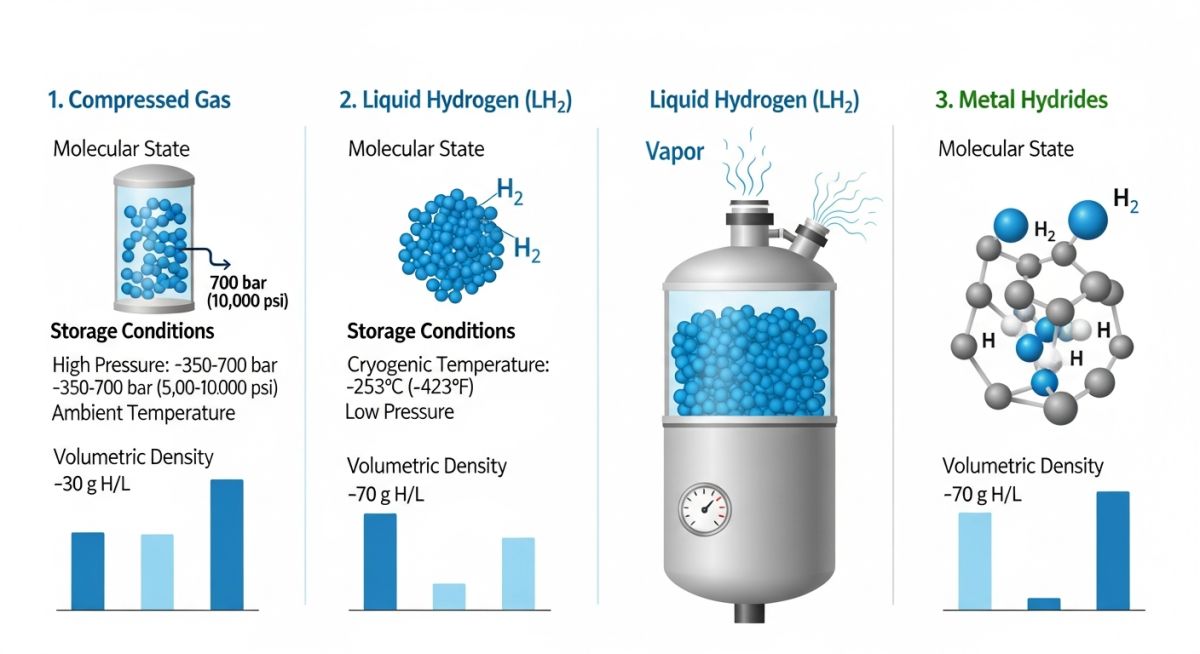
The table below provides a direct engineering comparison of the primary hydrogen storage methods. Use these values during your initial front-end engineering design (FEED) studies.
| Storage Method | Operating Pressure (bar) | Operating Temp (°C) | Volumetric Density (kg/m³) | Energy Penalty (% LHV) | Primary Design Code |
|---|---|---|---|---|---|
| Compressed Gas (Type I) | 150 – 200 | Ambient | 10 – 15 | 5 – 8% | ASME Sec VIII Div 1 |
| Compressed Gas (Type IV) | 350 – 700 | -40 to 85 | 23 – 40 | 10 – 15% | ASME Sec X / ISO 11119 |
| Cryogenic Liquid | 1 – 10 | -253 | 70.8 | 30 – 35% | ASME Sec VIII Div 1 / Div 2 |
| Metal Hydrides | 10 – 30 | 15 to 80 | 40 – 50 | 15 – 20% (Thermal) | ISO 16111 |
| LOHC (Dibenzyltoluene) | 1 – 5 | Ambient | 57 | 25 – 35% (Dehyd.) | ASME B31.3 |
This matrix maps key technical terms, acronyms, and physical parameters to their corresponding industry standards.
| Entity / Acronym | Technical Definition | Physical Parameter Impact | Applicable Standard |
|---|---|---|---|
| BOG (Boil-Off Gas) | Evaporated liquid hydrogen due to heat ingress. | Vessel pressure rise; requires venting or re-liquefaction. | NFPA 2 |
| HE (Hydrogen Embrittlement) | Loss of ductility and load-bearing capacity in metals. | Sub-critical crack growth under static tensile stress. | ASME B31.12 / ASTM G142 |
| LHV (Lower Heating Value) | Energy released by combusting a fuel, excluding water vaporization heat. | Determines net system efficiency (120.1 MJ/kg for H2). | ISO 14687 |
| MAWP | Maximum Allowable Working Pressure. | Defines pressure relief valve setpoints and wall thickness. | ASME Sec VIII Div 1 |
Implementing Hydrogen Storage Technologies Safely on Site
Before you introduce hydrogen into any newly constructed piping manifold or storage vessel, you must execute a strict pre-commissioning protocol. In my years on site, I have found that skipping even a minor step can lead to leaks that are incredibly difficult to locate once the system is fully pressurized.
Field Verification Checklist
Ensure all piping, fittings, and valves have certified Mill Test Reports confirming a minimum of 12% nickel content for 316/316L stainless steel to prevent hydrogen embrittlement.
Perform a pneumatic leak test using helium (at least 10% helium mixed with nitrogen) at 110% of the system MAWP. Hydrogen molecules are nearly as small as helium, making this the only reliable leak test.
Purge the system with high-purity nitrogen until the oxygen concentration inside the vessel and piping is verified to be below 1.0% by volume before introducing hydrogen.
Verify that optical UV/IR flame detectors and electrochemical or catalytic bead hydrogen gas detectors are calibrated, positioned correctly, and integrated with the emergency shutdown (ESD) system.
Measure the electrical resistance across all flanged joints. Ensure resistance is below 10 Ohms to prevent static electricity buildup, which can ignite escaping hydrogen.
Field Case Study: Real-World Application
The Problem: Micro-Leaks and Pressure Drop in a 350-Bar Manifold
During the commissioning of a green hydrogen refueling station, the operator noticed a persistent pressure drop of 1.5 bar per hour in the high-pressure buffer storage manifold (Type III cylinders operating at 350 bar). Standard bubble-solution leak testing at the threaded connections showed no signs of leakage. The project was stalled, and the team suspected a faulty cylinder liner, which would have cost over 150,000 to replace.
The Engineering Solution and Outcome
I was brought in to audit the system. First, we replaced the nitrogen-only pressure test with a 90/10 Nitrogen-Helium mix and used a mass spectrometer leak detector. We quickly identified three micro-leaks located at the instrument tubing connections. The original installer had used standard single-ferrule compression fittings instead of the dual-ferrule fittings specified in the design.
We replaced the incorrect fittings with high-quality 316L dual-ferrule fittings, re-torqued them to specification, and performed a successful helium leak test. The pressure drop was completely eliminated, saving the client from an unnecessary cylinder replacement and ensuring a safe, leak-free startup.
My Recommendation: Always mandate helium leak testing for any hydrogen system operating above 10 bar. Standard bubble tests are simply not sensitive enough to detect the micro-leaks that hydrogen can exploit.
Frequently Asked Engineering Questions
Why does hydrogen cause embrittlement in carbon steel?
What is the difference between Type III and Type IV hydrogen cylinders?
How is boil-off gas (BOG) managed in liquid hydrogen storage?
Why is helium used to leak test hydrogen systems instead of nitrogen?
What are the main safety considerations for indoor hydrogen storage?
How does the energy density of LOHC compare to compressed hydrogen?
===FAQ_BLOCK===
Complete Course on
Piping Engineering
Check Now
Key Features
- 125+ Hours Content
- 500+ Recorded Lectures
- 20+ Years Exp.
- Lifetime Access
Coverage
- Codes & Standards
- Layouts & Design
- Material Eng.
- Stress Analysis
