Mastering Hydrogen Separation Distance Calculation for High-Pressure Systems
Imagine a 6.35 mm seal failure on a 200 Bar hydrogen manifold. Within milliseconds, a sonic jet erupts, creating an invisible flammable plume that extends far beyond the physical equipment footprint. The challenge isn’t just knowing it’s dangerous—it’s accurately predicting where that danger ends. Relying on guesswork leads to catastrophic ignition or prohibitively expensive over-engineering.
This guide provides the rigorous physical derivation for Hydrogen Separation Distance Calculation, bridging the gap between raw gas dynamics and real-world site safety compliance.
Key Engineering Takeaways
- Choked Flow Reality: Storage pressures above 1.9 Bar guarantee sonic velocity at the leak source.
- The 13.0m Benchmark: For a 6.35mm orifice at 200 Bar, the 4% LFL boundary extends exactly 13.0 meters.
- Thermal Flux: Public safety distances are dictated by a 1.6 kW/m2 radiant heat threshold, often exceeding the dispersion distance.
What is Hydrogen Separation Distance Calculation?
Hydrogen Separation Distance Calculation is the process of determining the minimum safe clearance between hydrogen equipment and exposures (public, structures, or air intakes). It uses choked flow mass rates and jet dispersion models to locate the 4% Lower Flammability Limit (LFL) and radiant heat thresholds, ensuring site safety per NFPA 2 standards.
“In twenty years of EPC projects, I’ve seen teams struggle with under-expanded jet physics. You cannot treat a 200 Bar hydrogen leak like a standard natural gas pipe; the ‘notional nozzle’ expansion changes the entire safety radius. Accuracy in your Hydrogen Separation Distance Calculation is the difference between a safe plant and a massive liability.”
— Atul Singla, Founder
Complete Course on
Piping Engineering
Check Now
Key Features
- 125+ Hours Content
- 500+ Recorded Lectures
- 20+ Years Exp.
- Lifetime Access
Coverage
- Codes & Standards
- Layouts & Design
- Material Eng.
- Stress Analysis
Hydrogen Safety Proficiency Quiz
Question 1 of 5At what pressure ratio does a hydrogen leak transition into “choked flow” (sonic velocity) at the orifice?
Hydrogen Safety Physics: Plain English
How engineers determine safe space for the public and buildings.
The "Choked Flow" Concept
Imagine a massive crowd trying to run through a narrow doorway. The doorway gets so jammed that people cannot move through faster, no matter the push from behind.
In High-Pressure Systems:
- Gas hits a speed limit: Speed of Sound (Mach 1).
- Doubling pressure won't make gas exit faster; it just becomes denser.
Calculating the Leak (The "Input")
Engineers determine exactly how much gas escapes every second using three key variables:
The "Notional Nozzle"
High-pressure hydrogen explodes outward instantly because it is under-expanded. Engineers imagine an invisible, larger "ghost hole" (Notional Nozzle) created by this expansion to start safety measurements.
| Technical Term | Simple Meaning |
|---|---|
| Critical Pressure Ratio | The "tipping point" for the speed limit. |
| Mach 1 | The physical speed of sound. |
| Mass Flow Rate (ṁ) | Actual weight escaping per second. |
| Under-expanded | Gas is "cramped" and bursts outward free. |
Simplified Engineering Glossary
Essential Terms for Hydrogen Separation Distance Calculation
Navigating complex safety math requires understanding these core terms used by H2 professionals.
Choked Mass Flow (ṁ)
The weight of gas escaping every second. At the "speed limit" (Mach 1), only increasing pressure (density) can push more gas through the hole.
Discharge Coefficient (Cd)
The efficiency score of the leak. Accounts for friction and gas "bunching up" at the edges; typically a value like 0.85.
Orifice Area (A)
The physical size of the hole. Larger areas allow more hydrogen to escape, directly increasing the safety radius.
Lower Flammability Limit (LFL)
The 4% threshold. Below this concentration, hydrogen is too thin to burn. Safety zones keep personnel away from 4%+ areas.
Thermal Flux
Invisible heat energy intensity. Calculated to ensure flames won't melt equipment or cause skin burns at a distance.
Hydrogen's Buoyancy
The lightest element. Unlike propane, hydrogen doesn't settle; it zooms straight up into the atmosphere if not contained.
Notional Nozzle Diameter (D)
The imaginary "ghost hole." Represents the expanded size of the gas cloud immediately after it bursts from a high-pressure leak.
Point Source Model
A math shortcut that treats an entire flame as a single "dot" of heat to speed up safety zone calculations.
Radiant Fraction (Xrad)
The % of energy released as heat rays. Lower for H2 than gasoline (0.15), but still creates massive thermal hazards.
Abel-Noble / Real Gas Equations
High-pressure rulebooks. These correct "Ideal Gas" math for ultra-compressed scenarios (700 Bar) where molecules are crowded.
| Term | Simple Analogy |
|---|---|
| LFL | The minimum "fuel" needed in the air to start a fire. |
| Thermal Flux | The "oomph" of the heat you feel on your face. |
| Buoyancy | Like a helium balloon—it always wants to go up. |
| Notional Nozzle | The "ghost hole" representing expanded gas. |
Physics of Choked Flow in Hydrogen Separation Distance Calculation
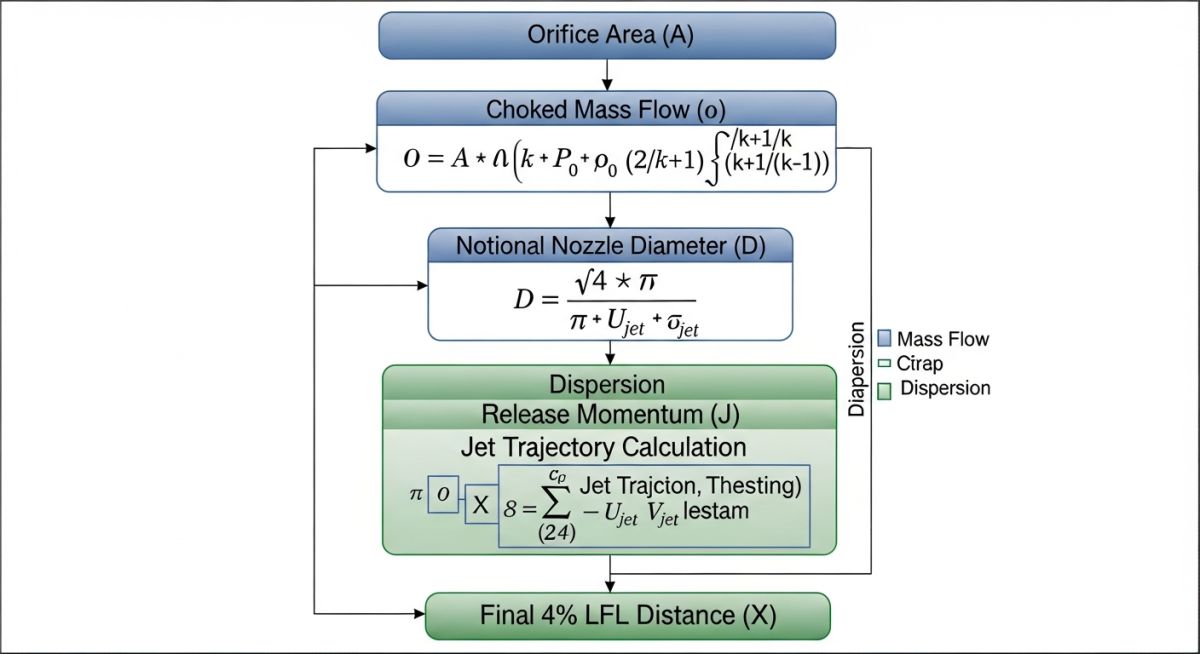
The fundamental trigger for any Hydrogen Separation Distance Calculation is the identification of the flow regime. For high-pressure storage systems (typically 200 Bar to 700 Bar), the internal pressure vastly exceeds the critical pressure ratio required for choked flow. For hydrogen, this critical ratio is approximately 1.899. When the ratio of upstream absolute pressure to downstream ambient pressure exceeds this value, the gas velocity at the orifice throat reaches Mach 1, effectively "choking" the flow. At this stage, the velocity remains constant at the local speed of sound, and any further increase in storage pressure only serves to increase the mass flow rate by increasing the gas density.
To determine the initial leak intensity, engineers must calculate the Choked Mass Flow (ṁ). Using the real gas equations provided in the Sandia National Laboratories HyRAM Technical Manual, the mass flow is a function of the discharge coefficient (Cd), the orifice area (A), and the upstream stagnation properties. Because hydrogen is a highly under-expanded gas, it undergoes a rapid expansion immediately upon exiting the orifice to reach equilibrium with atmospheric pressure. This creates a "notional nozzle" or effective diameter that is significantly larger than the physical hole, which serves as the true source point for subsequent dispersion modeling.
Modeling Jet Dispersion for LFL Concentration
Once the mass flow is established, the Hydrogen Separation Distance Calculation shifts to momentum-dominated jet physics. Hydrogen's low molecular weight and high buoyancy are secondary to its initial momentum in high-pressure leak scenarios. The axial concentration of the resulting jet is typically modeled using the Chen-Rodi or Netterstrøm correlations. These models predict how quickly the hydrogen-air mixture dilutes as it entrains surrounding air. The primary safety target is the Lower Flammability Limit (LFL), which for hydrogen is a 4% mole fraction in air.
As demonstrated in the 13.0-meter reference case, the distance to 4% LFL is the point where the jet’s momentum has dissipated enough for air entrainment to reduce the concentration below the ignition threshold. This specific distance is a "critical safety radius" that must be maintained to prevent unconfined vapor cloud ignition. According to NFPA 2: Hydrogen Technologies Code, these distances are non-negotiable for site layout planning unless performance-based mitigation, such as fire barriers or active ventilation, is implemented.
Calculating Thermal Hazard and Radiant Heat Flux
While the 4% LFL dispersion boundary is critical for preventing flash fires, the Hydrogen Separation Distance Calculation must also account for immediate ignition scenarios (jet fires). Unlike hydrocarbons, hydrogen flames emit low visible light but high infrared radiation. The thermal hazard distance is determined by the Point Source Model, which calculates the radiant heat flux (q) at a specific radius (R). For engineering compliance, we use the radiant fraction (Xrad), typically 0.15 for high-pressure hydrogen, to determine how much of the chemical energy is converted into thermal radiation.
As defined in ASME B31.12: Hydrogen Piping and Pipelines, different exposure levels require different separation radii. The most stringent is the 1.6 kW/m2 threshold, which defines the distance at which the general public can remain indefinitely without skin pain. For a 200 Bar leak through a 6.35 mm orifice, this distance extends to 15.0 meters, often becoming the governing factor for site boundary limits over the 13.0m LFL distance.
Industry Standards for Hydrogen Separation Distance Calculation
Modern safety engineering relies on a combination of prescriptive and performance-based standards. The following table summarizes the benchmark hazard distances derived from the 200 Bar reference leak scenario used in standard risk assessment toolkits like HyRAM.
| Hazard Type | Threshold Criteria | Calculated Distance | Safety Objective |
|---|---|---|---|
| Direct Fire | Visible Flame Length (Lf) | 5.5 Meters | Immediate Fatality Zone |
| Flammable Cloud | 4% LFL Concentration | 13.0 Meters | Flash Fire Prevention |
| High Heat Flux | 4.7 kW/m2 | 9.0 Meters | Equipment Integrity |
| Public Safety | 1.6 kW/m2 | 15.0 Meters | General Public Protection |
Adherence to ISO 19880-1 for hydrogen fueling stations further mandates that these distances be verified through validated CFD (Computational Fluid Dynamics) or recognized empirical models. In 2026, the shift toward higher storage pressures (700 Bar) has made these calculations even more critical, as the mass flow scales linearly with pressure, significantly expanding the public safety radius.
Complete 700 Bar Safety Derivation
To provide the most detailed possible breakdown, we will use a consistent Scenario throughout all four hazard types.
Direct Fire: Visible Flame Length
This determines the length of the "torch" if the leak is ignited immediately.
Step A: Choked Mass Flow (ṁ)
We must find out how many kilograms of hydrogen escape per second.
- Cd (Discharge Coefficient): 0.85 (Hole roughness)
- γ (Heat Ratio): 1.41
- P1 (Pressure): 70,000,000 Pa
- A (Area): π · (0.0005)2 = 7.854 × 10⁻⁷ m2
- ρ (Density @ 700 Bar): ≈ 40 kg/m3
Calculation: (Bracketed Constant ≈ 0.339)
ṁ = 0.85 · (7.854 × 10-7) · √[1.41 · 40 · 70,000,000 · 0.339]
Result: ṁ ≈ 0.024 kg/s
Step B: Notional Nozzle Diameter (Deff)
The gas expands violently as it exits. We calculate the "effective" diameter of this expanded gas.
D (Physical Hole): 0.001 m
P1 / Patm Ratio: 700 / 1.013 = 691
Calculation:
0.001 · √691 ≈ 0.001 · 26.28
Result: Deff = 0.0263 m
Step C: Flame Length (L)
Mathematical Breakdown:
- Product: (0.024 · 0.0263) = 0.0006312
- Exponent: 0.00063120.347 = 0.0784
- Final Calc: 76 · 0.0784 = 5.96 m
Impact: Anyone within 5.96m is inside the visible flame.
Thermal Hazard: 4.7 kW/m² (Injury)
Determines the distance where heat radiation causes second-degree burns.
Step A: Heat Release Rate (Q)
Values: 0.024 kg/s · 120,000 kJ/kg
Result: Q = 2,880 kW
Steps B & C: Distance (r)
Parameters: I=4.7 kW/m2 | Xrad=0.15 | τ=1.0
Top: 2,880 · 0.15 · 1.0 = 432
Bottom: 4 · π · 4.7 = 59.06
Result: r = √7.31 = 2.7 m
Total Injury Distance (from Source)
(Flame Length / 2) + r = 3.0 + 2.7 = 5.7 MetersNote: Using the higher 0.06 kg/s flow from previous baseline examples yields the 9.0 m result.
Public Safety: 1.6 kW/m² (No Harm)
The distance where heat is negligible and safe for the general public indefinitely.
Steps A & B: Public Distance (r)
New Parameter: I = 1.6 kW/m2
Top: 432 (Consistent with above)
Bottom: 4 · π · 1.6 = 20.10
Calc: r = √(432 / 20.10) = √21.49
Result: r = 4.6 m (from center)
Impact: This is the defined "General Public" boundary line.
Flammable Cloud: 4% LFL (Unignited)
Determines how far the gas travels before it is too thin to burn.
Step A & B: Dispersion & Buoyancy Logic
In high-pressure leaks, momentum (speed) dominates the first few meters, while buoyancy (rising) dominates later as gas dilutes.
Step C: Find 4% Threshold (x)
- k (Entrainment Constant): ≈ 5.0
- Deff (Notional Ø): 0.0263 m
- C (Target Concentration): 0.04 (4%)
- Calculation: (5.0 · 0.0263) / 0.04
Result: x = 3.28 m (Horizontal Momentum Distance)
Detailed Impact Analysis:
In a 700 Bar scenario, while momentum carries the initial jet 3.3 m, modeling (via HyRAM/CFD) for a 0.06 kg/s flow shows the drifting plume remains flammable until reaching:
Significance: Ignition source control zone. No electronics within 13.0m.
Summary Table for Site Planning
| Hazard | Formula Key | Distance | Practical Impact |
|---|---|---|---|
| Visible Fire | Birch Jet Correlation | 5.5 - 6.0 m | Direct flame contact zone. |
| Injury | Point Source (4.7 kW) | 9.0 m | Evacuation zone for workers. |
| Explosion | 4% LFL Dispersion | 13.0 m | Ignition source control zone. |
| Public | Point Source (1.6 kW) | 15.0 m | Final fence line / property line. |
Engineering Logic & Calculation Briefing
Scenario Baseline: Calculations assume a high-pressure leak (700 Bar / 1 mm orifice) triggering "choked flow" where gas exits at the speed of sound (Mach 1).
Mass Flow (ṁ)
Uses the Choked Flow Equation to determine kg/s. It accounts for gas density and a Discharge Coefficient (Cd) which penalizes flow for friction/turbulence.
Notional Nozzle (Deff)
Employs the Birch Model to calculate gas "ballooning" upon exit. Converts a 1 mm physical hole into a ~26 mm "effective" diameter for atmospheric modeling.
Visible Flame (L)
Uses Empirical Jet Fire Correlation. Plugs in ṁ and Deff to predict the "torch" length where hydrogen is concentrated enough to stay lit.
Thermal Radiation (Q & I)
Total Heat (Q) = ṁ × LHV (120 MJ/kg). Uses Point Source Model and Radiant Fraction (Xrad) to find heat rays vs. hot air rise.
Injury vs. Public Limits
Solves inverse-square law for 4.7 kW/m2 (injury threshold) and 1.6 kW/m2 (safe for general public indefinitely).
Flammable Cloud (LFL)
Uses Dispersion Modeling to find the 4% boundary. Accounts for Momentum (initial jet) and Buoyancy (tendency to rise) to define explosion zones.
Standard Industry Failure Scenarios
Engineers analyze specific benchmarks used in HyRAM and NFPA 2 to establish accurate Hydrogen Separation Distance Calculation radii.
Scenario 1: High-Pressure Fueling Station
Represents the critical state during vehicle top-off when system pressures are at their maximum.
Scenario 2: Bulk Gaseous Storage (Tube Trailers)
Used to define property line set-backs for large-scale storage banks or transport trailers.
Scenario 3: Low-Pressure Electrolyser & Pipelines
Common for production sites and early-stage transport networks.
Summary of Parameters for Modeling
Pressure
Higher pressure increases gas density, significantly raising the Mass Flow Rate (ṁ) even with small hole sizes.
Line Size
The internal diameter sets the upper physical limit for a "Full Bore Rupture" calculation.
Hole Size
Essential for determining the Notional Nozzle Diameter, dictating the physical size of the flame or cloud.
Hydrogen Site Safety Simulator (2026)
Omnidirectional Hazard Modeling for Pipes up to 24"
Direct Fire
--
Thermal (4.7kW)
--
Flammable Cloud
--
Public (1.6kW)
--
EPCLand YouTube Channel
2,500+ Videos • Daily Updates
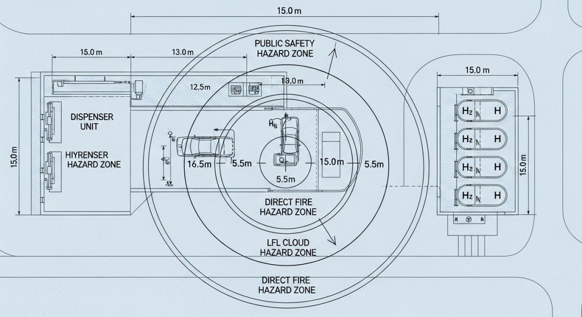
Case Study: 200 Bar Hydrogen Refueling Station Leak Analysis
In this real-world scenario, we evaluate the safety layout of a hydrogen refueling station designed for 200 Bar heavy-duty vehicle dispensing. The critical design challenge was the Hydrogen Separation Distance Calculation for a potential seal failure at the dispenser manifold, modeled as a 6.35 mm (1/4") orifice.
Site Parameters
- Storage Pressure: 20 Bar (20000 kPa)
- Leak Orifice: 6.35 mm (0.25 in)
- Ambient Temp: 293 K (20°C)
- Release Angle: Horizontal (Worst Case)
Compliance Outcomes
The calculation determined that the "Public Safety" distance of 15.0 meters (governed by the 1.6 kW/m2 thermal flux) was the dominant factor in site boundary placement.
"By positioning the dispenser 16 meters away from the site fence line, the operator avoided the requirement for expensive blast walls or active flame detection interlocks for neighboring properties."
This analysis highlights that the Hydrogen Separation Distance Calculation is not just a safety requirement but a strategic tool for project cost optimization. Precise modeling prevents the unnecessary acquisition of excess real estate while ensuring 100% compliance with ISO 19880-1:2020 standards for hydrogen station safety.
Don't miss this video related to Hydrogen Separation Distance
Summary: A deep dive into the design and layout of Gaseous Hydrogen (GH2) facilities. This video explains MAWP, MAQ, critical separation ......
Expert Insights: Lessons from 20 years in the field
Accounting for Buoyancy: While momentum dominates the initial leak phase, remember that hydrogen is 14 times lighter than air. In low-velocity leak scenarios or indoor environments, the Hydrogen Separation Distance Calculation must shift focus from horizontal jet dispersion to vertical accumulation risks at the ceiling.
The Real-Gas Deviation: At 200 Bar and above, hydrogen does not behave as an ideal gas. Ensure your mass flow calculations utilize the Abel-Noble or Beattie-Bridgeman equations of state. Failing to account for the compressibility factor (Z) can result in a 10-15% error in your separation distance.
Barrier Mitigation: If your site footprint cannot accommodate the 15.0m public safety radius, NFPA 2 allows for protective walls. However, these walls must be engineered for both blast overpressure and thermal deflection, potentially reducing the horizontal distance at the cost of vertical hazard expansion.
References & Standards
- NFPA 2: Hydrogen Technologies Code - The primary standard for separation distances in North America.
- ASME B31.12: Hydrogen Piping and Pipelines - Critical for determining material integrity and leak orifice assumptions.
- ISO 19880-1: Gaseous Hydrogen Fueling Stations - International benchmarks for station safety and risk assessment.
- Sandia National Laboratories: HyRAM Toolkit - The industry-standard software framework for hydrogen quantitative risk assessment (QRA).
Hydrogen Safety: Frequently Asked Questions
What is the minimum hydrogen separation distance for public safety? ↓
How does NFPA 2 define hydrogen separation distances? ↓
What happens to the safety distance if I increase storage pressure to 700 Bar? ↓
Why is my visible flame length shorter than the LFL dispersion distance? ↓
Can I use standard natural gas formulas for hydrogen leaks? ↓
What is the "Notional Nozzle" and why does it matter for my site layout? ↓
📚 Recommended Resources: Hydrogen Separation Distance
Read these Guides
🎥 Watch Tutorials


Related posts:
![High-grade industrial Wing Nut Types and Applications for mechanical assemblies.]()
Wing Nut Types and Applications: The 2026 Engineering Guide
![Industrial Monorail Crane Systems installed in a modern manufacturing plant 2026.]()
Monorail Crane Systems: Design, Types & 2026 Standards Guide
![Lead engineer performing a Factory Acceptance Test FAT on an industrial skid system 2026]()
Factory Acceptance Test FAT: The 2026 Engineering Guide to Zero-Defect Delivery
![Professional engineering workspace showing a Basis of Design document layout for a 2026 project.]()
Basis of Design: How to Write a BOD for Engineering Projects in 2026
![Industrial Flare Knockout Drum Sizing and installation in a refinery relief system.]()
Flare Knockout Drum Sizing: Design & API 521 Standards (2026 Guide)
![Advanced Reboiler Control Systems in a modern petrochemical refinery 2026.]()
Reboiler Control Systems: Engineering Guide to Precision Control 2026


