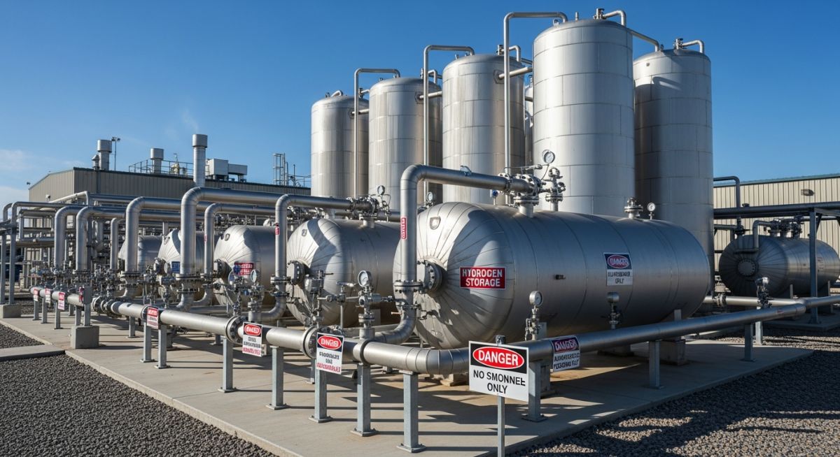
Mastering Hydrogen Safety in Industrial Facilities: Engineering and Design Guide
In my 20-plus years of designing piping systems for high-pressure gas applications, I have watched hydrogen transition from a niche chemical feedstock to the absolute forefront of the global clean energy transition. But let me be completely frank with you: hydrogen is an incredibly unforgiving molecule. It is the smallest, lightest, and most leak-prone element in existence. If you design a hydrogen system using the same rules of thumb you use for natural gas or propane, you are setting yourself up for a catastrophic field failure.
When I review piping and instrumentation diagrams (P&IDs) for modern hydrogen facilities, the first things I look for are not just the pipe schedules, but the fundamental safety layers. Hydrogen has an extremely wide flammability range (4% to 75% by volume in air) and an incredibly low minimum ignition energy of just 0.02 millijoules. A tiny static spark, or even the friction of a high-pressure leak escaping a flange, can ignite it. This guide is my attempt to download two decades of hard-won field experience directly into your design workflow, ensuring your facility remains safe, compliant, and highly efficient.
Key Engineering Takeaways
- Understand the physical properties of hydrogen, including its high diffusivity and low ignition energy, to design effective containment systems.
- Implement multi-layered leak detection strategies combining electrochemical, catalytic bead, and optical flame detectors.
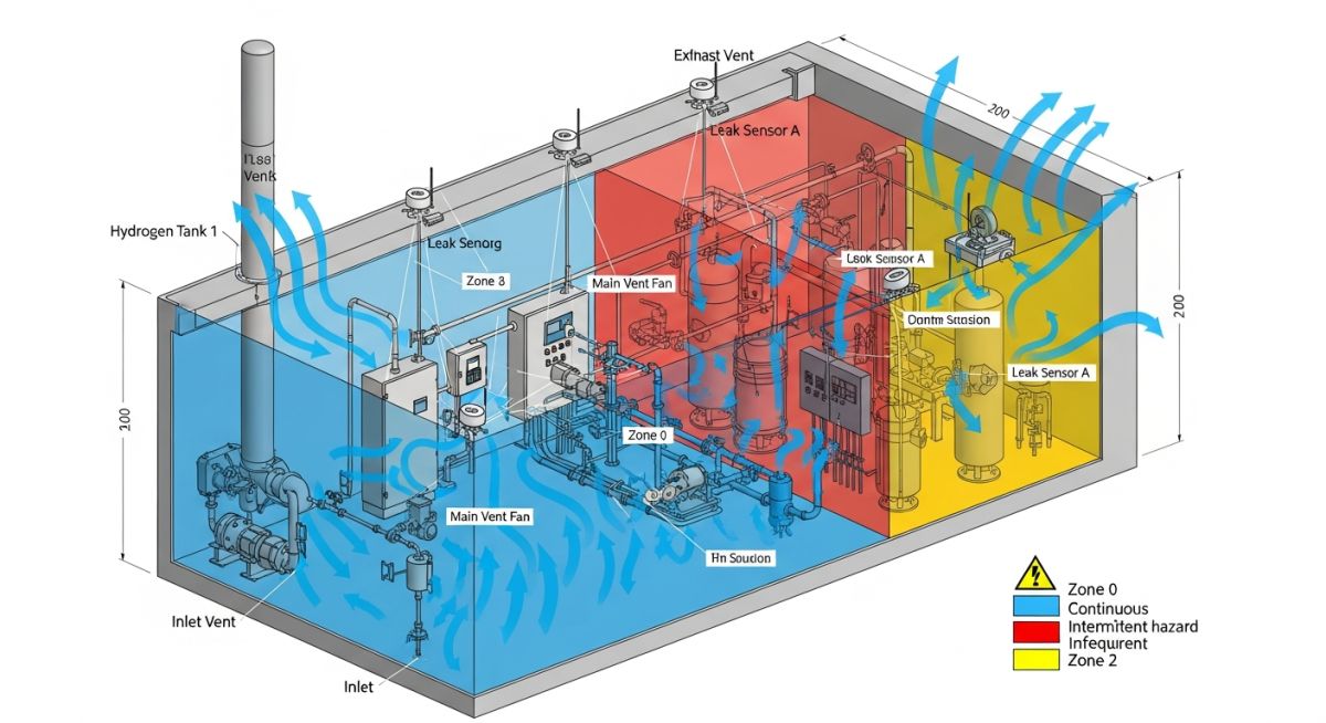
- Design ventilation systems that prevent hydrogen accumulation in high-point pockets and ceiling spaces.
- Apply strict hazardous area classifications in accordance with NFPA 2, API RP 500, and IEC 60079-10-1.
- Select materials carefully to prevent hydrogen embrittlement, prioritizing high-nickel stainless steels like 316/316L.
Why Hydrogen Safety in Industrial Facilities Demands Precision
To design a safe facility, we must first look at the physics of the molecule. Hydrogen’s density is only about 7% of air’s density. This means that when a leak occurs, the gas rises rapidly at a velocity of up to 9 meters per second. While this high buoyancy is a massive advantage in open-air environments—where the gas quickly disperses upward—it becomes a major hazard indoors. If your facility has unventilated ceiling pockets, structural I-beams, or roof peaks, hydrogen will trap there, quickly reaching explosive concentrations.
Calculating Sonic Leak Rates for Hydrogen
When hydrogen escapes from a high-pressure line, the flow is almost always choked (sonic). This occurs because the upstream pressure is significantly higher than the atmospheric pressure. To size your ventilation systems and determine the placement of your detectors, you must calculate the mass flow rate of a potential leak.
The choked mass flow rate through a sharp-edged orifice can be calculated using the following standard thermodynamic equation:
Where:
- m_dot = Mass flow rate of the leak (kilograms per second)
- Cd = Discharge coefficient of the leak orifice (dimensionless, typically 0.62 for a sharp-edged pinhole)
- A = Area of the leak orifice (square meters)
- P1 = Upstream absolute pressure (Pascals)
- k = Ratio of specific heats for hydrogen (1.41 at 20 degrees Celsius, dimensionless)
- MW = Molecular weight of hydrogen (0.002016 kilograms per mole)
- R = Universal gas constant (8.314 Joules per mole-Kelvin)
- T1 = Upstream temperature (Kelvin)
Let us walk through a real-world design scenario. Suppose we have a hydrogen buffer vessel operating at 350 bar (35,000,000 Pascals) at a temperature of 293 Kelvin (20 degrees Celsius). We want to calculate the leak rate through a 1.0-millimeter diameter pinhole in a weld joint.
First, calculate the cross-sectional area of the leak:
Next, substitute the values into our choked flow equation:
Let’s break down the terms inside the square root:
Term B = (2 / 2.41)^(2.41 / 0.41) = (0.82987)^5.878 = 0.3334
Combined inside square root = 1.1669 * 10^-6 * 0.3334 = 3.89 * 10^-7
Square root value = 0.0006237
Now, multiply by the external terms:
This 1 mm pinhole leak results in a continuous release of 10.6 grams of hydrogen per second. While 10.6 grams sounds small, at standard temperature and pressure, this equates to approximately 127 liters of gas per second escaping into your facility. If this occurs in an enclosed compressor room, it will reach the lower flammability limit in seconds without massive, immediate ventilation.
In my years of auditing plants, I still see engineers specifying standard ASTM A106 Grade B carbon steel pipes for high-pressure hydrogen service. This is a recipe for disaster. Atomic hydrogen dissolves into the metal lattice, causing severe embrittlement and micro-cracking. Always specify materials compliant with ASME B31.12, such as 316/316L stainless steel with a minimum nickel content of 12% to ensure structural integrity under high pressures.
Designing Dilution Ventilation Systems
To prevent a leak of this magnitude from forming an explosive cloud, we must design a dilution ventilation system. The goal is to maintain the average hydrogen concentration below 25% of the Lower Flammability Limit (LFL). Since the LFL of hydrogen is 4.0% by volume, our target concentration (C) must not exceed 1.0% (0.01 volume fraction).
The required volumetric airflow rate (Q) for dilution ventilation is calculated as:
Where:
- Q = Required fresh airflow rate (cubic meters per second)
- V_leak = Volumetric leak rate of hydrogen at room temperature (cubic meters per second)
- S = Safety factor (typically 4.0 for industrial facilities to account for imperfect mixing)
- C_target = Target concentration limit (0.01 for 25% of LFL)
Using our calculated leak rate of 127 liters per second (0.127 cubic meters per second):
This means your ventilation fans must move 50.8 cubic meters of air per second (approximately 107,000 CFM) to safely dilute a single 1 mm pinhole leak in that room. This calculation highlights why we must combine ventilation with rapid, automated isolation valves to shut off the hydrogen source immediately upon leak detection.
To design safe systems, we must compare the physical properties of hydrogen against other common industrial gases. The table below outlines these critical differences, highlighting why hydrogen requires specialized engineering controls.
| Physical Property | Hydrogen (H2) | Methane (CH4) | Propane (C3H8) |
|---|---|---|---|
| Lower Flammability Limit (LFL) | 4.0% by volume | 5.0% by volume | 2.1% by volume |
| Upper Flammability Limit (UFL) | 75.0% by volume | 15.0% by volume | 9.5% by volume |
| Minimum Ignition Energy (MIE) | 0.02 millijoules | 0.28 millijoules | 0.25 millijoules |
| Autoignition Temperature | 585 degrees Celsius | 540 degrees Celsius | 450 degrees Celsius |
| Gas Density (Air = 1.0) | 0.07 | 0.55 | 1.52 |
| Diffusion Coefficient in Air | 0.61 square cm/sec | 0.16 square cm/sec | 0.10 square cm/sec |
This matrix maps the core technical entities, structural acronyms, physical parameters, and hyperlinked standard references required for a compliant hydrogen facility design.
| System Component | Applicable Code / Standard | Design Limit / Parameter | Engineering Action Required |
|---|---|---|---|
| Piping & Tubing | ASME B31.12 | Min 12% Nickel content for SS | Specify 316/316L; avoid high-strength carbon steels. |
| Ventilation Systems | NFPA 2 / IBC | Min 1.0 CFM/sq ft or 25% LFL dilution | Install continuous exhaust fans with backup power. |
| Electrical Equipment | NFPA 70 (NEC) / IEC 60079 | Class I, Division 1/2, Group B / IIC | Specify explosion-proof enclosures and intrinsically safe circuits. |
| Leak Detection | ISA 92.00.01 | Alarm at 10% LFL; shutdown at 25% LFL | Position electrochemical and catalytic sensors at high points. |
| Pressure Relief | API RP 520 / ASME Sec VIII | Sized for fire exposure and blocked flow | Route relief lines to a safe outdoor vent stack with flame arrestors. |
Pre-Commissioning Hydrogen Safety Checklist
Before you introduce a single molecule of hydrogen into a newly constructed or modified piping system, you must execute a rigorous pre-commissioning protocol. In my experience, most start-up incidents occur because of simple installation errors—such as reversed check valves, loose flange bolts, or uncalibrated gas detectors. Use this checklist to verify your facility’s safety systems before startup.
Field Verification Steps
-
Helium Leak Testing (ASME V Article 10): Perform a high-sensitivity helium leak test on all mechanical joints. Because helium is the closest inert molecule to hydrogen in size, it is the only acceptable gas for verifying joint tightness. Do not rely solely on nitrogen bubble tests for high-pressure systems.
-
Electrical Grounding and Bonding (NFPA 77): Verify that all piping segments, vessels, and structural steel are electrically bonded and grounded to earth. Measure the resistance to ground; it must be less than 10 Ohms to prevent static charge accumulation.
-
Detector Calibration and Placement: Physically verify that all hydrogen gas detectors are installed at the highest points of the room, within 12 inches of the ceiling. Calibrate each sensor using a certified span gas and verify that the alarm relays trigger the emergency ventilation and isolation valves.
-
Emergency Shutdown Valve (ESD) Stroke Testing: Perform a full-stroke test on all automated isolation valves. Verify that the fail-safe position (typically fail-closed) is achieved within the specified safety response time (usually less than 2.0 seconds).
-
Vent Stack Integrity: Inspect the outdoor vent stack to ensure it discharges vertically upward without any obstructions, rain caps, or bends. Verify that the flame arrestor is correctly installed and that the stack is grounded.
Implementing Hydrogen Safety in Industrial Facilities Safely
To illustrate the critical importance of proper engineering controls, let us look at a real-world project I audited in 2022. A green hydrogen production facility experienced a series of micro-leaks that could have resulted in a major explosion if not for the multi-layered safety systems we implemented during the design phase.
The Problem: Chronic Micro-Leaks in a Compressor Room
A newly commissioned hydrogen compressor station operating at 450 bar experienced chronic micro-leaks at the high-pressure flange connections. Because the room was designed with standard natural gas ventilation parameters (6 air changes per hour, with exhaust registers located mid-wall), hydrogen gas began to accumulate in the dead spaces between the ceiling I-beams.
Within three hours of continuous operation, a localized hydrogen pocket reached a concentration of 12% by volume (well within the explosive range). A maintenance technician entering the room noticed a faint, high-pitched whistling sound—the classic sign of a high-pressure gas leak—but the room’s standard gas detectors, which were mounted 5 feet off the floor, read 0% LFL.
The Outcome: Redesign and Safety Integration
We immediately shut down the system and implemented a comprehensive engineering redesign. First, we replaced all standard RF flanges with ring-type joint (RTJ) flanges and specified spiral-wound gaskets with 316SS inner rings. Second, we redesigned the ventilation system, increasing the air changes to 30 per hour and installing dedicated exhaust hoods directly above the compressor skids.
Finally, we installed continuous electrochemical and catalytic bead detectors at the highest ceiling points, interlocked with the main safety PLC. If any detector senses 10% LFL, the ventilation system ramps up to maximum speed. If the concentration reaches 25% LFL, the automated ESD valves close, isolating the hydrogen source in less than 1.5 seconds. Since these modifications, the plant has operated safely for over four years without a single safety incident.
Direct Engineering Recommendation
Never rely on a single layer of protection. A safe hydrogen facility must utilize the “Defense in Depth” principle: robust mechanical containment (ASME B31.12), rapid automated isolation (ESD), continuous high-point monitoring, and active dilution ventilation. If any one of these layers fails, the others must be capable of preventing a catastrophic event.
Frequently Asked Engineering Questions
What is the difference between ASME B31.3 and ASME B31.12 for hydrogen piping?
Why is helium used for leak testing hydrogen systems instead of nitrogen?
How does hazardous area classification differ for hydrogen compared to natural gas?
What are the specific material requirements to prevent hydrogen embrittlement?
How do you size a relief valve for liquid hydrogen storage systems?
What is the recommended response time for hydrogen gas detectors?
Complete Course on
Piping Engineering
Check Now
Key Features
- 125+ Hours Content
- 500+ Recorded Lectures
- 20+ Years Exp.
- Lifetime Access
Coverage
- Codes & Standards
- Layouts & Design
- Material Eng.
- Stress Analysis


