What is a High Integrity Pressure Protection System (HIPPS)?

Imagine a scenario where your upstream production pressure suddenly surges beyond the design limits of your downstream piping. Your traditional Pressure Relief Valves (PRVs) are designed to vent that excess to the flare, but the resulting radiation and environmental impact in 2026 are no longer acceptable. Why is your facility still relying solely on mechanical venting when a High Integrity Pressure Protection System (HIPPS) could isolate the source in milliseconds?
In this definitive guide, we move beyond the basics of overpressure protection. We will deconstruct the 1oo3 sensor voting logic, calculate the exact Safety Integrity Level (SIL) requirements, and explore how a High Integrity Pressure Protection System (HIPPS) serves as the ultimate electronic barrier between your high-pressure assets and a catastrophic loss of containment.
Key Takeaways
- ✓ Architecture: Understand why a 1oo3 (One-out-of-three) voting logic is the industry standard for high-availability sensor arrays.
- ✓ Safety Credits: Learn how to leverage a High Integrity Pressure Protection System (HIPPS) to reduce flare header sizing under API 521.
- ✓ Response Time: Master the calculation for total loop response time including initiator, logic solver, and final element.
Defining HIPPS
A High Integrity Pressure Protection System (HIPPS) is a type of Safety Instrumented System (SIS) designed to prevent overpressure by shutting off the source of high pressure rather than releasing it to the atmosphere. It typically consists of three pressure sensors, a safety logic solver, and two dedicated isolation valves, ensuring a SIL 3 performance level.
“In my 20 years of EPC experience, the most common mistake engineers make is treating a HIPPS like a standard ESD loop. A true High Integrity Pressure Protection System must be autonomous, fast-acting, and strictly compliant with the 2-second response rule for gas service. Don’t compromise on your final element selection.”
— Atul Singla, Founder of Epcland
Complete Course on
Piping Engineering
Check Now
Key Features
- 125+ Hours Content
- 500+ Recorded Lectures
- 20+ Years Exp.
- Lifetime Access
Coverage
- Codes & Standards
- Layouts & Design
- Material Eng.
- Stress Analysis
Loading Question…
Assessment Complete!
You have completed the High Integrity Pressure Protection System technical audit.
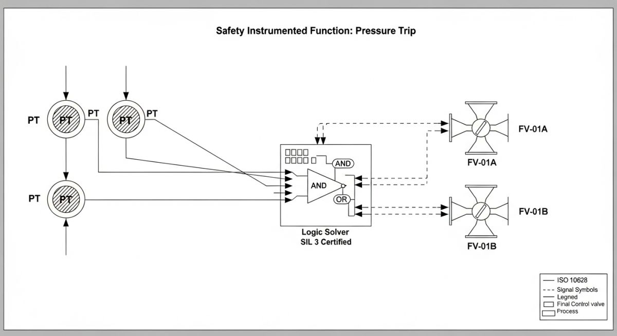
Typical Architecture of a High Integrity Pressure Protection System (HIPPS)
The fundamental architecture of a High Integrity Pressure Protection System (HIPPS) is built upon the principle of functional independence and high availability. Unlike standard process control loops, a HIPPS is a dedicated Safety Instrumented System (SIS) that serves as the final barrier against overpressure. The system is comprised of three distinct subsystems: the Initiator (Sensors), the Logic Solver, and the Final Control Element (Valves).
In modern engineering designs for 2026, the High Integrity Pressure Protection System (HIPPS) typically employs a 2oo3 (Two-out-of-three) voting logic for sensors. This configuration is mathematically optimized to provide the highest level of safety integrity while virtually eliminating “nuisance trips” that lead to costly production downtime. By requiring two transmitters to agree on an overpressure condition before initiating a shutdown, the system remains resilient even if a single sensor fails or drifts.
HIPPS Sensors: Utilizing Triple Modular Redundancy (TMR)
The “eyes” of the High Integrity Pressure Protection System (HIPPS) are its pressure transmitters. To achieve SIL 3 compliance, these sensors must be safety-certified (IEC 61508) and typically utilize Triple Modular Redundancy (TMR). In a TMR setup, three independent transmitters monitor the same process point.
Engineers must pay close attention to Common Cause Failures (CCF). If all three transmitters are of the identical make and model, a systematic design flaw could theoretically disable all three simultaneously. To mitigate this, high-integrity designs often utilize “diverse redundancy,” selecting transmitters from different manufacturers or utilizing different sensing technologies to ensure the High Integrity Pressure Protection System (HIPPS) remains robust against shared failure modes.
Furthermore, the physical tapping points for these sensors must be designed to prevent plugging or hydrate formation, which are common issues in high-pressure gas service. Heat tracing and chemical injection points are often integrated directly into the sensor manifold to maintain the high availability required by the system’s Safety Requirement Specification (SRS).
Logic Solver Requirements for High Integrity Pressure Protection System
The Logic Solver is the “brain” of the High Integrity Pressure Protection System (HIPPS). It is a safety-rated PLC (Programmable Logic Controller) that is physically and logically separated from the Basic Process Control System (BPCS). This separation is a non-negotiable requirement of the IEC 61511 standard.
For a High Integrity Pressure Protection System (HIPPS) to perform its function in 2026, the logic solver must feature a scan time of less than 50 milliseconds. It process inputs from the 2oo3 sensor voting block and, upon detection of a trip condition, de-energizes the digital outputs linked to the final control valves. Modern logic solvers also provide advanced diagnostics, monitoring the health of the loop’s wiring (line monitoring) and detecting internal hardware faults in real-time, immediately alerting operators via the plant’s HMI while maintaining the safety state.
Final Control Elements: High Integrity Pressure Protection System (HIPPS) Valves
The final control element of a High Integrity Pressure Protection System (HIPPS) is arguably the most critical component, as it must physically block the flow of high-pressure fluid. In 2026, the industry standard for SIL 3 applications involves two isolation valves in series, typically arranged in a 1oo2 (One-out-of-two) voting configuration for shutdown. This ensures that if one valve fails to close due to a mechanical obstruction or “stuck” stem, the second valve provides the necessary barrier.
Unlike standard emergency shutdown valves, High Integrity Pressure Protection System (HIPPS) valves are equipped with high-performance actuators—usually pneumatic or hydraulic—designed for rapid stroking. Because the system must often close within 2 seconds to prevent a downstream rupture, the use of quick-exhaust valves and high-flow solenoids is mandatory. Furthermore, these valves must meet strict “Tight Shut-Off” (TSO) requirements, typically Class VI or better, to ensure zero leakage during a high-pressure surge.
Integration and High Integrity Pressure Protection System Interfaces
Interfacing a High Integrity Pressure Protection System (HIPPS) requires a delicate balance between safety isolation and operational visibility. While the logic solver must remain autonomous, it provides critical status data to the Distributed Control System (DCS). In 2026, this is achieved through safety-rated communication protocols or hardwired signals that relay “Health,” “Trip Status,” and “Bypass Active” alarms to the control room.
Calculating Safety Integrity Level (SIL) for HIPPS
To validate a High Integrity Pressure Protection System (HIPPS) design, engineers must perform a PFD (Probability of Failure on Demand) calculation. This determines the Risk Reduction Factor (RRF) the system provides.
Risk Reduction Equation
RRF = 1 / PFDavg
Note: For SIL 3, RRF must be between 1,000 and 10,000.
Total Response Time
Ttotal = Tinitiator + (TIO + Tscan) + Tvalve
Ensure Ttotal < Process Safety Time (PST).
HIPPS Regulatory Standards & Comparison
Compliance with ASME Section VIII (Code Case 2211) and API 521 allows for the use of HIPPS as a substitute for traditional pressure relief devices, provided the safety integrity is rigorously documented.
| Feature | Mechanical PRV | HIPPS (SIL 3) |
|---|---|---|
| Primary Function | Pressure Relief (Venting) | Pressure Isolation (Source) |
| Environmental Impact | High (Flare/Emission) | Zero (Containment) |
| Maintenance | Bench Test (Offline) | Partial Stroke Test (Online) |
| Applicable Standard | ASME Section I/VIII | IEC 61511 / IEC 61508 |
EPCLand YouTube Channel
2,500+ Videos • Daily Updates
HIPPS Total Response Time Calculator (2026)
Calculate the loop response time to verify it falls within the Process Safety Time (PST) according to IEC 61511 standards.
Typical: 50ms – 300ms for Pressure Transmitters.
Includes CPU scan and I/O module delay.
Mechanical closure time of final elements.
Maximum allowable time before rupture/hazard.
High Integrity Pressure Protection System (HIPPS) Failure Case Study
In a recent 2026 technical audit of an offshore gas platform, a High Integrity Pressure Protection System (HIPPS) failed to meet its mandatory SIL 3 performance during a scheduled proof test. The system, designed to protect a 12-inch subsea pipeline, exhibited a “Fail-to-Close” (FTC) state in one of the two series isolation valves.
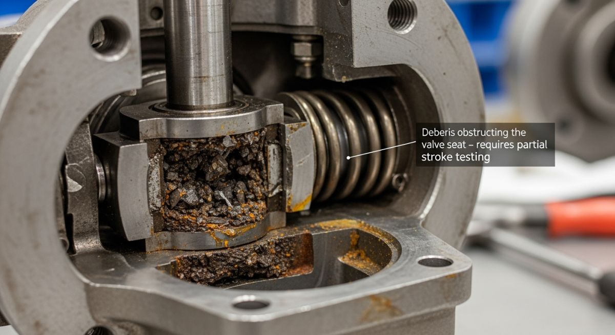
Root Cause Analysis
- Mechanical Stiction: Calcium carbonate buildup on the valve stem prevented full closure.
- Maintenance Gap: The Partial Stroke Testing (PST) interval was extended beyond the manufacturer’s recommendation.
- Logic Solver Latency: A 150ms delay in the digital output module further eroded the safety margin.
2026 Remediation Strategy
- Automated PST: Implemented a weekly automated Partial Stroke Test via the smart positioner.
- Diverse Redundancy: Replaced the secondary valve with a different seat design to mitigate common cause failure.
- Updated SRS: Recalculated the PFD with higher demand rates based on real-world process transients.
Outcome: By addressing the valve stiction and improving the diagnostics of the High Integrity Pressure Protection System (HIPPS), the operator achieved a 40% improvement in the calculated RRF (Risk Reduction Factor), maintaining the plant’s social license to operate under 2026 environmental regulations.
Expert Insights: Lessons from 20 years in the field
- ● Final Element Oversizing: In 2026, we see many engineers oversizing HIPPS actuators for “safety.” However, excessive torque can damage valve stems during high-speed closure. Always match actuator torque to the Break-to-Open (BTO) and Running torque requirements specifically.
- ● The PST Myth: Partial Stroke Testing (PST) is not a replacement for a Full Proof Test. While PST improves your PFDavg by detecting stuck-at-open failures, it cannot verify the Tight Shut-Off (TSO) capability of the High Integrity Pressure Protection System (HIPPS).
- ● Independence is King: Ensure your HIPPS has a dedicated UPS and independent instrument air headers. A shared utility failure shouldn’t disable your last line of defense.
High Integrity Pressure Protection System (HIPPS) FAQ
Can a HIPPS completely replace a Pressure Relief Valve (PRV)?
Yes, under ASME Section VIII and API 521, a High Integrity Pressure Protection System (HIPPS) can replace a PRV if it is designed to be as safe as the valve it replaces. This usually requires a SIL 3 rating and rigorous documentation for local regulatory approval.
What is the standard response time for a HIPPS in gas service?
Typically, the total loop response time (from sensor detection to 100% valve closure) must be less than 2 seconds for gas applications to prevent the pressure wave from reaching downstream equipment.
Does HIPPS require a separate logic solver?
According to IEC 61511, the High Integrity Pressure Protection System (HIPPS) must be physically and logically independent from the Basic Process Control System (BPCS) to prevent common-mode failures.
Why is 2oo3 voting used for HIPPS transmitters?
2oo3 (Two-out-of-three) voting provides a balance between high safety (any two sensors can trip) and high plant availability (one sensor can fail without causing a nuisance trip).
How do 2026 regulations impact HIPPS design?
In 2026, there is a heavier focus on cyber-security (IEC 62443) and environmental reporting. Modern High Integrity Pressure Protection System (HIPPS) units now require encrypted logic communication and automated data logging for flare-reduction credits.
What is “Stiction” and why is it dangerous for HIPPS?
Stiction occurs when a valve remains in one position for so long that the static friction exceeds the actuator’s starting force. For a High Integrity Pressure Protection System (HIPPS), this is a “dormant failure” that could prevent the valve from closing during an overpressure event.
References & Standards
📚 Recommended Resources: Piping Engineering
Read these Guides
🎓 Advanced Training


Related posts:
![High-grade industrial Wing Nut Types and Applications for mechanical assemblies.]()
Wing Nut Types and Applications: The 2026 Engineering Guide
![Industrial Monorail Crane Systems installed in a modern manufacturing plant 2026.]()
Monorail Crane Systems: Design, Types & 2026 Standards Guide
![Lead engineer performing a Factory Acceptance Test FAT on an industrial skid system 2026]()
Factory Acceptance Test FAT: The 2026 Engineering Guide to Zero-Defect Delivery
![Professional engineering workspace showing a Basis of Design document layout for a 2026 project.]()
Basis of Design: How to Write a BOD for Engineering Projects in 2026
![Industrial Flare Knockout Drum Sizing and installation in a refinery relief system.]()
Flare Knockout Drum Sizing: Design & API 521 Standards (2026 Guide)
![Advanced Reboiler Control Systems in a modern petrochemical refinery 2026.]()
Reboiler Control Systems: Engineering Guide to Precision Control 2026


