Table of Contents
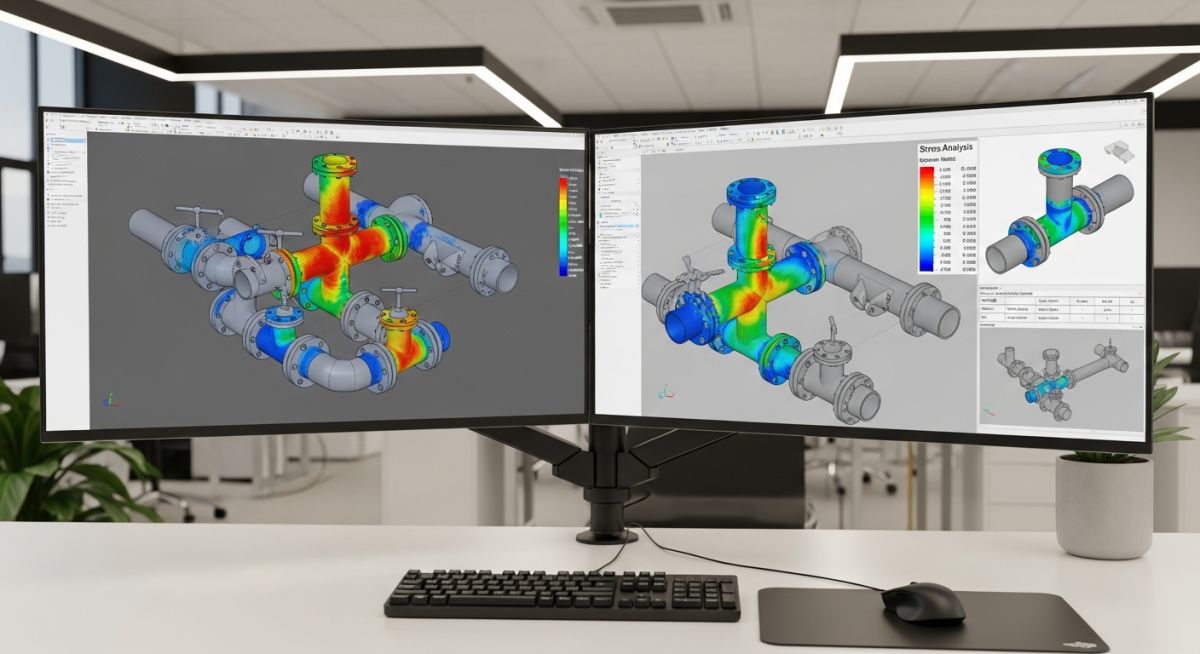
Stress Analysis of GRP / GRE / FRP Piping using START-PROF
In my 20 years of piping engineering, I have seen many engineers treat Glass Reinforced Plastic (GRP) and Glass Reinforced Epoxy (GRE) piping as if it were carbon steel with a lower modulus. This is a recipe for catastrophic field failures. Composite materials are anisotropic; their strength properties vary significantly between the axial and hoop directions.
When we design these systems, we must abandon isotropic assumptions. Software like START-PROF has revolutionized how we execute these complex calculations. It provides a dedicated, code-compliant environment that natively understands the orthotropic nature of composites, the critical impact of winding angles, and the strict requirements of ISO 14692.
What You Will Master in This Guide:
- The fundamental differences between isotropic steel and orthotropic GRP/GRE materials.
- How to configure START-PROF for accurate composite piping stress modeling.
- Step-by-step implementation of ISO 14692 stress envelope limits.
- Practical methods for managing thermal expansion and support spacing in non-metallic systems.
Why GRP Piping Stress Analysis Matters
Unlike carbon steel, which exhibits uniform physical properties in all directions, GRP, GRE, and FRP are composite laminates. Their mechanical behavior depends heavily on the glass fiber winding angle, resin type, and fiber-to-resin ratio. A typical filament-wound pipe has a winding angle of approximately 55 degrees. This specific angle is optimized to handle internal pressure, providing a hoop-to-axial strength ratio of roughly 2:1.
When performing calculations, we must define separate elastic moduli: the Axial Tensile Modulus (Ea) and the Hoop Tensile Modulus (Eh). In my project experience, ignoring this distinction leads to massive errors in thermal expansion and displacement calculations.
Do not use the nominal wall thickness for stress calculations. GRP pipes have a structural wall thickness and a non-structural liner (corrosion barrier). In START-PROF, you must input the structural wall thickness (ts) for stress calculations, while using the total nominal thickness for weight and clearance checks. Failing to do this underpredicts actual stresses by up to 30%.
The ISO 14692 Stress Envelope
ISO 14692 does not use a single allowable stress value like ASME B31.3 does for metals. Instead, it utilizes a trapezoidal long-term design envelope. This envelope maps the interaction between axial stress and hoop stress.
The stress state of the pipe at any node must fall within this calculated boundary. The envelope is derived from the Long-Term Hydrostatic Strength (LTHS) of the laminate, modified by several service factors:
f_part = A_factor * B_factor * C_factor * G_factor
Where:
- A_factor: Chemical resistance factor based on the fluid medium.
- B_factor: Fatigue factor for cyclic operations.
- C_factor: Temperature derating factor.
- G_factor: System design factor (typically 0.82 for general applications).
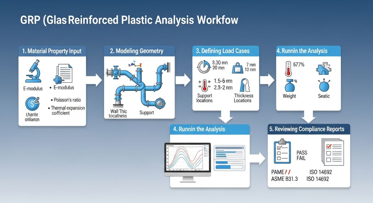
Thermal Expansion and Support Spacing
The axial thermal expansion coefficient of GRP is roughly twice that of carbon steel. However, because the axial modulus of GRP is significantly lower (about 10% to 15% of steel), the thermal forces generated on anchors are much lower.
This low modulus means the pipe is highly flexible but also highly susceptible to buckling and excessive sagging. Support spans for GRP must be much shorter than those for steel. I always recommend using the continuous span tables provided by the manufacturer or calculating them directly in START-PROF to limit deflection to 1/2 inch or 0.5% of the span length.
Executing GRP Piping Stress Analysis Successfully
To ensure accurate simulation results, we must input precise physical properties. The table below compares typical design parameters for GRP, GRE, and FRP against standard Carbon Steel. These values highlight why specialized software is required.
| Property Description | GRP (Polyester) | GRE (Epoxy) | FRP (Vinyl Ester) | Carbon Steel (A106-B) |
|---|---|---|---|---|
| Axial Elastic Modulus (Ea) | 9,500 – 12,000 MPa | 11,000 – 15,000 MPa | 10,000 – 13,000 MPa | 203,000 MPa |
| Hoop Elastic Modulus (Eh) | 18,000 – 22,000 MPa | 20,000 – 26,000 MPa | 19,000 – 24,000 MPa | 203,000 MPa |
| Poisson’s Ratio (v_ah) | 0.35 – 0.38 | 0.36 – 0.40 | 0.35 – 0.39 | 0.30 |
| Thermal Expansion (Axial) | 2.0e-5 mm/mm/°C | 1.8e-5 mm/mm/°C | 2.1e-5 mm/mm/°C | 1.2e-5 mm/mm/°C |
| Density (Specific Gravity) | 1.7 – 1.9 g/cm³ | 1.8 – 2.0 g/cm³ | 1.7 – 1.9 g/cm³ | 7.85 g/cm³ |
Technical Mapping & Specifications Matrix
The following matrix maps the critical software inputs required by START-PROF to ensure compliance with international standards like ISO 14692 and ASME B31.3.
| Entity / Acronym | Physical Parameter | START-PROF Input Field | Standard Reference |
|---|---|---|---|
| LTHP | Long-Term Hydrostatic Pressure | Design Pressure Envelope | ISO 14692 Clause 5.3 |
| E_axial | Axial Tensile Modulus | Elastic Modulus (X-axis) | ASTM D2105 / ISO 14692 |
| v_ha | Poisson’s Ratio (Hoop/Axial) | Poisson’s Ratio (XY) | ISO 14692 Annex G |
| alpha_a | Axial Thermal Expansion | Thermal Expansion Coeff. | ASTM D696 |
| f_part | Partial Design Factor | Service Factor / Derating | ISO 14692 Clause 5.4 |
GRP Piping Stress Analysis Checklist
Before executing any stress run in START-PROF, I require my design team to complete this verification checklist. This process prevents common modeling errors that lead to incorrect stress outputs and potential field failures.
START-PROF Modeling Verification Steps:
-
Verify Structural Wall Thickness: Ensure that the corrosion barrier (liner) thickness is subtracted from the nominal wall thickness in the stress calculation input.
-
Confirm Winding Angle: Check that the correct filament winding angle (typically 54 to 60 degrees) is defined, as this directly dictates the ratio of axial to hoop properties.
-
Apply Temperature Derating: Ensure the axial and hoop tensile moduli are derated for the maximum design temperature using the manufacturer’s data sheets.
-
Model Support Gaps and Friction: GRP is highly sensitive to local stresses. Ensure all guide supports are modeled with a minimum 2mm to 3mm gap and realistic friction coefficients (typically 0.3 for GRP-on-steel, or 0.1 if PTFE sliding plates are used).
-
Validate Soil Stiffness (for Buried Lines): If modeling buried GRP lines, verify that the soil spring stiffness values are calculated using the correct soil modulus (E’sb) and trench backfill parameters.
Field Case Study: Real-World Application
During commissioning of a seawater intake system at a Middle East desalination plant, multiple adhesive-bonded joints on a DN 600 GRE line failed. The original design team had performed a simplified stress analysis using software that treated the GRE as an isotropic material with a single elastic modulus.
They failed to account for the low axial modulus and high thermal expansion rate. As a result, the thermal expansion of the line caused severe bending moments at the elbows, overstressing the rigid adhesive joints and causing them to shear.
My team was brought in to troubleshoot. We re-modeled the entire system in START-PROF using the ISO 14692 module. By inputting the correct orthotropic properties (Ea = 12,500 MPa, Eh = 24,000 MPa) and the actual winding angle of 55 degrees, we identified that the axial stresses at the joints exceeded the ISO 14692 envelope by 145%.
To resolve this, we optimized the support configuration. We replaced several rigid guides with sliding supports lined with PTFE to reduce friction. We also introduced a series of expansion loops to absorb the axial thermal growth without transferring high bending moments to the joints. The re-modeled system passed all code compliance checks in START-PROF.
Direct Recommendation: Never bypass orthotropic material inputs. If your software does not support native orthotropic modeling with a trapezoidal stress envelope, switch to a platform like START-PROF that does. It is the only way to guarantee the long-term integrity of composite piping networks.
Frequently Asked Engineering Questions
How does START-PROF calculate the stress envelope for GRP piping?
What is the significance of the winding angle in GRE piping stress analysis?
How do soil-structure interactions affect buried GRP piping in START-PROF?
Why can we not use standard ASME B31.3 metallic stress limits for GRP?
How does water hammer affect GRP piping systems compared to steel?
What is the role of joint efficiency factors in ISO 14692 compliance?
Complete Course on
Piping Engineering
Check Now
Key Features
- 125+ Hours Content
- 500+ Recorded Lectures
- 20+ Years Exp.
- Lifetime Access
Coverage
- Codes & Standards
- Layouts & Design
- Material Eng.
- Stress Analysis

📚 Recommended Resources: GRP piping stress analysis
Read these Guides



Related posts:
![Infographic flowchart of the GRP GRE FRP piping stress analysis workflow in START-PROF.]()
Rigid Struts: Definition, Applications, and Modeling in Caesar II
![Industrial centrifugal pump installed on a concrete foundation with precision piping and alignment.]()
How to Use a Pump Installation Checklist for Maximum Reliability
![3D Caesar II pipe stress analysis model of a centrifugal pump piping system showing stress distribution.]()
Pump-Piping Alignment Caesar II Stress Analysis Methodology
![3D render of a structural steel cross-bracing connection with a gusset plate.]()
Mastering Steel Connections with a Cross-Bracing Design Example
![Industrial engineer checking shaft alignment on a centrifugal pump during commissioning.]()
How to Use a Pump Commissioning Checklist for Start-Up
![3D FEA model of a piping system showing modal analysis vibration shapes and stress distribution.]()
What Is Modal Analysis? Caesar II Piping Modal Analysis Steps