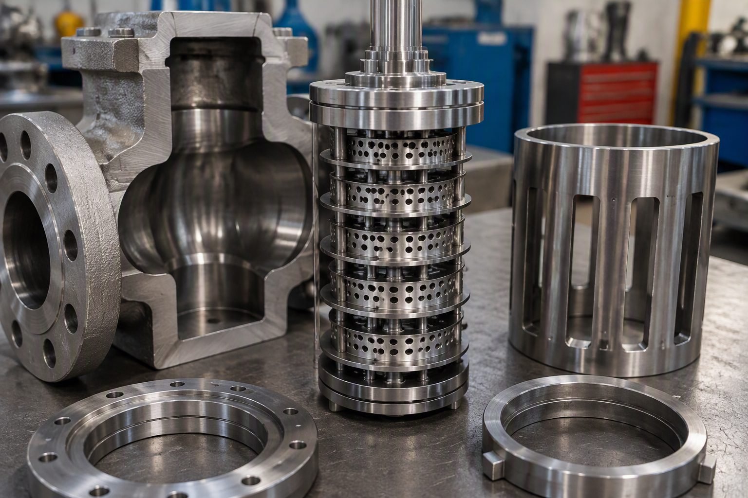
Globe vs Ball Valve: Trim Geometry and Performance
In my 20 years of piping design, I have seen countless projects suffer from premature valve failure simply because a designer selected a valve based on line size rather than trim physics. Walking through a process plant, you can immediately hear the screaming cavitation of a ball valve forced into throttling service, or see the weeping packing of a globe valve cycled too frequently. Understanding the mechanical differences between these two geometries is not just academic; it is a field survival skill.
- Globe valves excel at precise flow control but introduce high permanent pressure loss.
- Ball valves provide rapid, bubble-tight isolation with minimal flow resistance.
- ASME B16.34 wall thickness and pressure-temperature ratings dictate the mechanical limits of both designs.
Globe vs Ball Valve Trim Mechanics
Trim Geometry Differences: The mechanical design of valve internals dictates how fluid kinetic energy is dissipated or preserved during operation. Linear globe trims control flow by varying the narrow annular area between a plug and a stationary seat ring, while rotary ball trims rotate a spherical port to establish a straight-through flow path.
To understand the performance limits of these valves, we must look at the flow coefficient (Cv) and the liquid pressure recovery factor (FL). The flow coefficient represents the volume of water in gallons per minute that will flow through a wide-open valve with a pressure drop of 1 psi. Globe valves inherently have a much lower Cv for a given line size because the fluid must make two sharp 90-degree turns to pass through the seat.
This tortuous path increases the permanent pressure loss across the valve. In contrast, a full-port ball valve presents an unobstructed cylindrical path that matches the inside diameter of the pipe. This results in an exceptionally high Cv and near-zero pressure drop, making the ball valve highly efficient for fluid transport but poorly suited for energy dissipation.
The liquid pressure recovery factor (FL) describes a valve’s ability to recover static pressure downstream of the vena contracta (the point of minimum flow area and maximum velocity). Globe valves feature a high FL, typically ranging from 0.85 to 0.90. This means that as fluid passes through the restriction, the pressure drop is gradual, and a significant portion of the static pressure is not recovered, which keeps the downstream pressure relatively stable.
Ball valves have a low FL, often between 0.50 and 0.60 when partially open. This low recovery factor indicates that the static pressure drops sharply at the restriction and then recovers rapidly downstream. This rapid pressure recovery is the primary driver of cavitation in liquid systems, as vapor bubbles formed at the vena contracta collapse violently when the pressure rises above the vapor pressure limit.
How Cavitation Limits Throttling Performance
Cavitation Index Limits: Cavitation occurs when local static pressure drops below the vapor pressure of the liquid, forming bubbles that collapse violently downstream. Managing this phenomenon requires selecting trim geometries with high pressure-recovery coefficients to prevent structural erosion.
To evaluate the risk of cavitation in your piping system, you must calculate the operating cavitation index (sigma) using the following formula:
sigma = (P1 – Pv) / (P1 – P2)
Where P1 is the upstream static pressure (psia), P2 is the downstream static pressure (psia), and Pv is the vapor pressure of the fluid at operating temperature (psia). If the calculated sigma is less than the valve’s manufacturer-specified cavitation index, cavitation will occur.
Let us look at a practical example. Consider a water system where the upstream pressure (P1) is 145 psia, the downstream pressure (P2) is 45 psia, and the vapor pressure (Pv) at 60 degrees Fahrenheit is 0.26 psia.
sigma = (145 – 0.26) / (145 – 45) = 144.74 / 100 = 1.45
A standard ball valve throttled to a 30-degree opening angle typically has a cavitation threshold of 1.5 to 2.0. Because our calculated system sigma of 1.45 is lower than this threshold, a ball valve in this application would experience severe cavitation, leading to rapid trim destruction. A globe valve, with its higher resistance to cavitation and a threshold often below 1.2, would easily handle these operating conditions without damage.
ASME B16.34 Globe vs Ball Valve Standards
Standard Compliance Criteria: Pressure-temperature ratings and wall thickness limits must strictly adhere to standardized material groups to ensure pressure boundary integrity. These criteria prevent catastrophic shell failures under extreme operating conditions.
Both valve types must comply with the design requirements of ASME B16.34, which defines pressure-temperature ratings, minimum wall thickness, and testing protocols. The minimum wall thickness (t) for a valve body is calculated based on the pressure class and the inside diameter of the flow passage.
For carbon steel valves (such as ASTM A216 Grade WCB) in Material Group 1.1, the allowable stress values drop significantly as temperatures rise. This requires thicker body walls for high-temperature steam service, where globe valves are most commonly applied.
Furthermore, seat leakage testing must be performed in accordance with FCI 70-2. Globe valves typically achieve Class IV leakage (0.01% of rated valve capacity) with metal-to-metal seats, whereas soft-seated ball valves easily achieve Class VI leakage, which requires completely bubble-tight shutoff. This makes ball valves the superior choice for positive isolation in hazardous chemical lines.
Comparative Performance Tradeoffs: Selecting between linear and rotary valve designs requires balancing precise flow control against pressure recovery and sealing efficiency. Each geometry presents distinct mechanical advantages and operational limitations under high-pressure conditions.
Trim Design Advantages
- Globe valves offer precise, repeatable linear flow profiling with minimal hysteresis.
- Ball valves provide rapid quarter-turn operation, ideal for emergency shutdown (ESD) systems.
- Ball valves feature a full-bore design that matches pipe ID, resulting in near-zero pressure drop.
- Globe valves allow for multi-stage pressure drops to mitigate severe cavitation and aerodynamic noise.
- Ball valves achieve bubble-tight Class VI shutoff using resilient soft seats.
Trim Design Disadvantages
- Globe valves introduce massive parasitic energy losses due to their tortuous flow path.
- Standard ball valves suffer from rapid seat erosion and localized cavitation when used for throttling.
- Globe valves require massive, expensive linear actuators to overcome high process differential pressures.
- Ball valves can trap pressurized fluid within the body cavity, posing a thermal expansion hazard.
- Globe valves are prone to packing wear due to the continuous sliding motion of the stem.
Industrial Application Mapping: Matching valve trim geometry to specific process conditions prevents premature mechanical failure and optimizes system efficiency. Operating parameters such as fluid state, pressure drop, and cycle frequency dictate the ideal valve selection.
Valve Engineering Data Table: Globe vs Ball Valve Performance Metrics
Evaluating industrial valve performance requires examining operational coefficients, pressure ratings, and flow characteristics governed by standards such as ASME B16.34 and ISA 75.01. The engineering data table below details key performance metrics, pressure classes, and mechanical limitations for standard industrial globe and ball valves across typical process plant applications.
Reviewing these parameters helps piping engineers select appropriate trim configurations to avoid cavitation, high pressure drop, and premature seat degradation.
| Parameter / Metric | Globe Valve (Plug Trim) | Ball Valve (Floating/Trunnion) |
|---|---|---|
| Primary Service Duty | Precise flow throttling and pressure control | Bi-directional isolation (on-off service) |
| Flow Coefficient (Cv Efficiency) | Low to Moderate (tortuous S-flow path) | Extremely High (full-bore straight-through flow) |
| Design Code Compliance | ASME B16.34 / MSS SP-85 | ASME B16.34 / API 6D |
| Shut-Off Leakage Class | FCI 70-2 Class IV to VI (Soft/Metal) | FCI 70-2 Class VI (Bubble-tight soft seat) |
| Actuation Torque Requirement | High linear thrust (multiturn stem) | High breakaway torque (quarter-turn) |
| Cavitation Susceptibility | Moderate to High across high pressure drops | Low (unsuitable for partial opening throttling) |
Careful comparison of these operational limits ensures that piping systems comply with required safety standards and process efficiency targets.
Technical Mapping & Specifications Matrix
Understanding the structural and chemical interactions within industrial valve assemblies requires mapping core entities against accepted industrial standards. The matrix below correlates valve components, metallurgical designations, and applicable codes to assist engineers during detailed design reviews.
Each mapping entry references recognised testing protocols and manufacturing specifications to guarantee material traceability and structural reliability under extreme service conditions.
| Entity / Component | Structural Material | Governing Standard | Operational Function |
|---|---|---|---|
| Globe Valve Plug Trim | ASTM A276 Type 410 / Stellite Hardfaced | ASME B16.34 | Modulates flow area via linear stem travel |
| Ball Valve Spherical Trim | ASTM A182 F316 / Chrome Plated | API 6D | Provides quarter-turn on-off flow isolation |
| Valve Body Pressure Shell | ASTM A216 WCB / ASTM A351 CF8M | ASME B16.34 | Contains internal fluid pressure safely |
| Soft Seat Rings | PTFE / RPTFE / PEEK Composites | FCI 70-2 | Ensures bubble-tight seating contact stress |
| Stem Packing Assembly | Flexible Graphite / Braided PTFE | EPA Method 21 | Prevents fugitive atmospheric emissions |
Proper selection of these entity parameters guarantees compliance with plant safety mandates and environmental emission thresholds.
Site Verification Checklist: Globe vs Ball Valve Installation
[Valve Installation Verification]: Ensuring proper field installation of globe and ball valves requires strict adherence to ASME B31.3 piping code requirements and manufacturer guidelines. I always enforce a rigorous site verification routine before handing over piping loops to commissioning teams.
Use the structured checklist below during pre-commissioning walkthroughs to verify correct valve orientation, actuator alignment, and pressure rating compatibility.
Pre-Commissioning Valve Inspection Protocol
- Flow Direction Verification: Confirm globe valve body arrow matches process flow direction to prevent upward media pressure against the plug bottom.
- Actuator Clearance Check: Verify that ball valve quarter-turn handles or globe valve handwheels have full unobstructed range of motion without pipe insulation interference.
- Flange Bolt Torque Validation: Inspect flange bolting torque values against ASME PCC-1 guidelines using calibrated torque wrenches.
- Trim Material Traceability: Cross-check valve nameplate material grades (e.g., F316 trim) against piping material specifications (PMS) documents.
- Cavitation Risk Assessment: Confirm that pressure drop ratios across throttling globe valves do not exceed flashing thresholds defined in ANSI/ISA-75 standards.
- Emissions Testing Check: Verify fugitive emission packing gland tightness per EPA Method 21 standards on volatile hydrocarbon services.
Completing these verification steps minimizes operational hazards, eliminates premature seal failures, and ensures long-term plant mechanical integrity.
Field Case Study: Resolving Cavitation and Seat Erosion in Hydrocarbon Control Loops
[Case Study Background]: During a major refinery expansion project, a high-pressure hydrocarbon let-down control loop experienced severe vibration, acoustic noise, and rapid trim failure within three weeks of commissioning.
The Problem Encountered:
An incorrectly specified standard soft-seated ball valve was installed in throttling service to regulate a 45 bar differential pressure drop.
- Partial opening of the spherical ball trim created high-velocity jet streams eroding the soft PTFE seat rings.
- Pressure drop across the narrow opening triggered flashing and severe cavitation, damaging the downstream piping wall.
- High hydrodynamic forces caused stem vibration, leading to premature packing box leakage and fugitive emission failures.
- The operational team could not achieve stable flow modulation due to erratic hydrodynamic torque on the ball surface.
The Engineering Outcome & Resolution:
The engineering team replaced the unsuited ball valve with a contoured-plug globe valve conforming to ASME B16.34 standards.
- Installed a multi-stage staggered plug trim to dissipate fluid energy and eliminate localized cavitation inception.
- Upgraded trim metallurgy to Stellite hardfaced stainless steel, extending service life beyond five years.
- Achieved stable, linear flow modulation across the entire 10% to 90% control valve stroke range.
- Eliminated excessive pipeline vibration and restored fugitive emissions compliance below 500 ppmv.
Recommendation: Never use ball valves for continuous throttling duty where differential pressure exceeds critical vaporization thresholds; always deploy multi-stage globe valve trims for high-energy pressure reduction.
Frequently Asked Engineering Questions
Can a standard ball valve be used for continuous throttling applications?
No, standard ball valves are not designed for continuous throttling because the high-velocity fluid quickly degrades the soft seats.
- Localized erosion occurs rapidly on the exposed edge of the spherical ball.
- Cavitation risks increase significantly when the valve operates at openings below 30 percent.
- Flow control becomes highly non-linear, which destabilizes the control loop.
How does ASME B16.34 govern the wall thickness of globe vs ball valves?
The ASME B16.34 standard mandates minimum wall thickness based on pressure rating and material group.
- Globe valves require thicker bodies to handle asymmetric stress profiles from the internal bridge wall.
- Ball valves feature more symmetrical bodies but must account for seat cavity pressure relief.
- Both designs must pass hydrostatic shell tests at 1.5 times the pressure rating.
Why do globe valves exhibit a much higher pressure drop than ball valves?
The internal flow path of a globe valve forces the fluid to make two sharp 90-degree turns.
- This tortuous path creates high turbulence and frictional energy loss.
- Full-port ball valves offer an unobstructed, straight-through path with minimal resistance.
- The resulting loss coefficient of a globe valve is significantly lower.
What is the primary cause of seat leakage in globe vs ball valves?
Seat leakage stems from different mechanical wear patterns in each valve type.
- Globe valves suffer from plug misalignment, scale deposition on the flat seat, or wire-drawing.
- Ball valves experience seat deformation, particulate entrapment, or thermal expansion binding.
- Regular cycling helps clear debris from ball seats but can accelerate globe plug wear.
When should a piping engineer specify a needle valve instead of a globe valve?
Needle valves are specified for extremely low flow rates and precise metering applications.
- They utilize a highly tapered, slender plug for fine adjustments.
- Standard globe valves are suited for larger volumetric flows and coarser control.
- Needle valves are typically limited to smaller line sizes, usually under 2 inches.
Field Recommendation
Based on my 20 years of piping engineering experience, selecting between these two designs requires a strict evaluation of your process conditions rather than upfront cost. I recommend implementing the following field rules on your next project:
- If your process requires continuous flow regulation or operates under high pressure drops, select a globe valve with hardened trim (such as Stellite) to prevent erosion and cavitation damage.
- For tight shut-off in hydrocarbon or utility lines where pressure drop must be minimized, install a full-port ball valve with reinforced PTFE or metal seats depending on the operating temperature.
- In high-temperature thermal cycling services, avoid soft-seated ball valves entirely; instead, specify a metal-seated globe valve or a high-performance metal-seated ball valve with cavity relief to prevent thermal binding.
- When dealing with slurry or particulate-laden fluids, avoid standard globe valves as solids will accumulate in the seat pocket; instead, use a segmented ball valve which shears through media and self-cleans during operation.
Complete Course on
Piping Engineering
Check Now
Key Features
- 125+ Hours Content
- 500+ Recorded Lectures
- 20+ Years Exp.
- Lifetime Access
Coverage
- Codes & Standards
- Layouts & Design
- Material Eng.
- Stress Analysis
