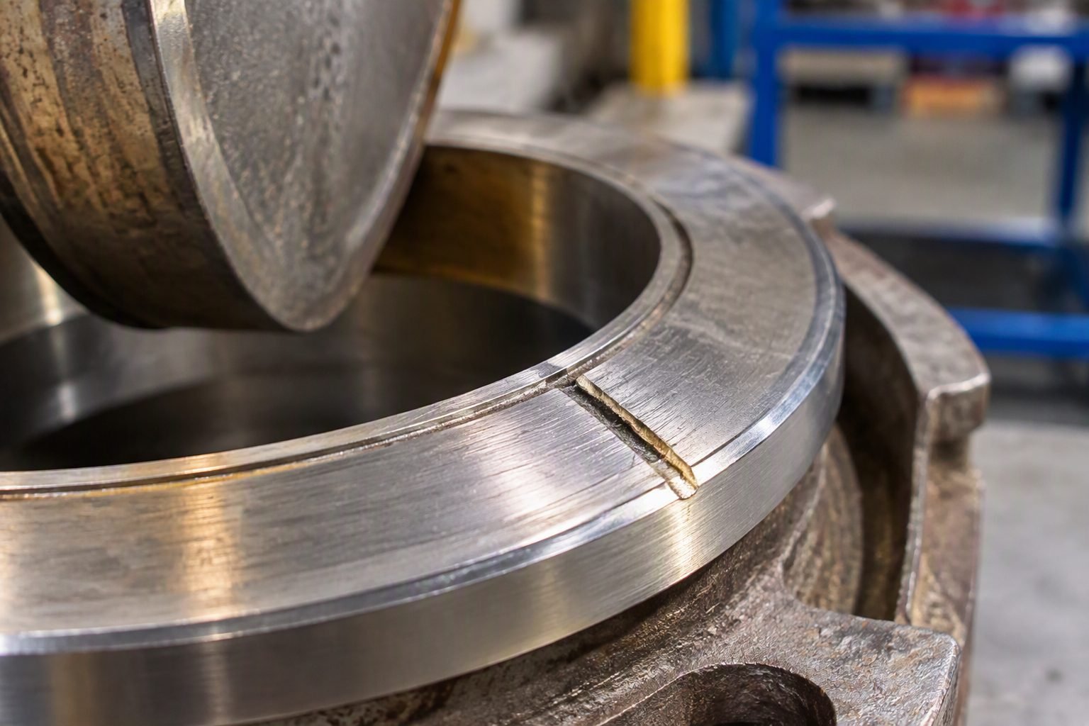
Why Gate Valve Throttling Destroys Piping Systems Through Seat Erosion
In my two decades walking process plants across the globe, I still wince whenever I spot an operator cranking a gate valve handle to a thirty percent opening to curb line pressure. That visible red position indicator might trick you into thinking you have dialed in a neat fluid choke, but inside that wedge cavity, a destructive metallurgical war is waging. Gate valves are strictly designed for binary isolation—on or off. When subjected to continuous intermediate throttling, high-velocity fluid jets slice through the narrow crescent opening like an industrial plasma torch.
Plant reliability groups frequently trace catastrophic steam, hydrocarbon, and slurry leakage back to this exact misapplication. Understanding the fluid mechanics behind wire-drawing and seat erosion is essential for protecting expensive alloy trims and preventing unplanned shutdown events across high-energy piping networks.
Key Engineering Takeaways
- Gate valves are strictly isolation devices governed by ASME design parameters and must never be used for continuous flow modulation.
- Partial disc exposure generates localized high-velocity fluid jets that erode wedge seating surfaces through wire-drawing.
- Vibration induced by flow clipping accelerates stem packing fatigue and guide rail wear.
- Proper piping design requires installing globe, butterfly, or control valves when throttling is mandatory.
The Fluid Mechanics of Gate Valve Throttling and Wire-Drawing
Wire-drawing mechanism definition: The severe abrasive wear pattern caused by high-pressure, high-velocity fluid leaking or forcing through a restricted clearance, cutting deep grooves into metal valve seating surfaces.
When a flexible or solid wedge gate valve is throttled to a partially open position, the flow area transforms from a full circular bore into an eccentric crescent shape. According to basic fluid continuity equations, constricting this flow area while maintaining system throughput forces the fluid velocity to accelerate dramatically through the opening. This high-velocity jet creates a massive pressure drop right across the seating interface, frequently initiating localized flashing and cavitation if vapor pressure thresholds are crossed.
Hydrodynamic Forces Acting on the Wedge
The exposed edge of a gate valve wedge acts like an airfoil in a high-speed wind tunnel when placed in a throttled stream. As the fluid impacts the upstream face of the wedge and accelerates through the narrow gap, uneven pressure distributions push the disc against the downstream guide ribs.
- Side-Load Stress: High differential pressure forces the wedge firmly into the downstream seating face, generating high frictional sliding loads during actuation.
- Vortex Shedding: The unstable wake behind the partially retracted wedge causes high-frequency mechanical oscillation of the stem and gate assembly.
- Particle Impact: Any entrained solid particles in the process fluid act like abrasive grit in a sandblaster, shearing away metal micro-structures at the seat ring interface.
Critical Design Warning
Never rely on a gate valve for differential pressure reduction or flow control. Operating outside API 600 operational guidelines voids manufacturer warranties and can cause sudden pressure boundary failure due to seat ring separation.
Metallurgical Degradation and Stellite Hardfacing Loss
To combat wear, high-pressure gate valves often feature Stellite cobalt-base alloy hardfacing welded onto the wedge and body seat rings. While Stellite offers exceptional hardness and corrosion resistance, it is not indestructible. When subjected to continuous liquid impingement at velocities exceeding 30 meters per second, the protective passive oxide film on the alloy surface is continuously stripped away. This exposes virgin metal to accelerated electrochemical corrosion and mechanical erosion, quickly cutting deep channels into the sealing face.
Once a microscopic groove or wire-draw path forms across the seating surface, leakage rates escalate exponentially. The high-velocity leak path concentrates the full line differential pressure across a tiny cross-section, guaranteeing complete seat destruction within hours or days of continuous throttling operation.
Advantages & Disadvantages of Gate Valve Operational Limits
Operational capability summary: Gate valves excel exclusively as full-bore isolation barriers but fail completely when subjected to flow modulation tasks due to hydrodynamic instability.
Advantages (When Used Properly)
- Provides virtually zero flow resistance and pressure drop when fully open.
- Offers bi-directional shutoff capability in clean liquid and gas service.
- Features a tight wedge-to-seat sealing design compliant with API 598 leakage criteria.
- Requires minimal pipeline space compared to bulky globe or diaphragm valve bodies.
- Accommodates pigging operations smoothly without internal obstruction.
Disadvantages (During Throttling)
- Extremely prone to rapid wire-drawing and seat erosion when partially open.
- Exhibits highly non-linear flow characteristics, making precise control impossible.
- Subject to severe disk vibration, chatter, and internal component fatigue.
- Requires high actuation torque if operated under unbalanced differential pressure.
- Prone to thermal binding if closed hot and allowed to cool in service.
Real-World Applications and Proper Valve Selection
Proper valve deployment: Correct industrial piping design mandates strict separation between isolation duties assigned to gate valves and modulation duties assigned to specialized control valves.
Refinery Main Fractionator Bottoms Isolation
Heavy residue hydrocarbon transfer lines utilize heavy-duty slab and wedge gate valves for absolute block service during turnaround operations. These valves remain in a fully open position for months or years, preventing erosion, and are actuated only when absolute zero-leakage isolation is required for maintenance safety sign-off.
High-Pressure Boiler Feedwater Systems
Power plant feedwater headers employ large-diameter forged steel gate valves for pump discharge isolation. Operators are strictly trained never to crack these valves to fill down-stream lines slowly; instead, small bypass globe valve loops are installed specifically to equalize pressure safely without destroying the main valve seats.
Long-Distance Crude Oil Transmission Pipelines
Mainline pump stations rely on massive pipeline gate valves to section off segments for emergency repair. Their full-bore design allows pigging tools to pass unobstructed while ensuring bubble-tight shutoff, provided they are never operated in intermediate throttling positions.
Cryogenic Liquefied Natural Gas Storage Terminals
LNG transfer systems use extended-bonnet gate valves to handle liquid fluid at negative 162 degrees Celsius. Because seat material thermal contraction is severe at cryogenic temperatures, throttling these valves would instantly score the soft seat inserts, leading to catastrophic fugitive emissions and safety hazards.
Gate Valve Throttling Performance Metrics and Erosion Thresholds
Gate valve throttling performance is fundamentally constrained by fluid dynamics and mechanical design limitations outlined in ASME B16.34. When an operator positions a gate valve at partial openings, high-velocity fluid jets accelerate through the restricted crescent-shaped orifice, creating intense turbulence and localized pressure drops that trigger rapid cavitation and material loss.
The empirical data compiled in the engineering reference matrix below highlights the direct correlation between percentage valve opening, fluid velocity acceleration across the disc, seating surface pressure drops, and corresponding expected degradation rates in severe hydrocarbon service environments governed by API 600 manufacturing specifications.
| Valve Opening (%) | Orifice Velocity Factor | Pressure Drop Ratio (Delta P / P1) | Erosion Risk Level | Applicable Standard |
|---|---|---|---|---|
| 100% (Full Open) | 1.0x (Baseline) | Less than 0.02 | Negligible | API 600 |
| 50% Partial Open | 3.8x Acceleration | 0.35 to 0.50 | High / Moderate | ASME B16.34 |
| 30% Throttling Position | 7.5x Acceleration | 0.70 to 0.85 | Severe (Wire-Drawing) | API 598 |
| 10% Near Closure | 14.2x Acceleration | Greater than 0.90 | Critical Seat Destruction | ASME B16.34 |
Reviewing these metrics confirms that operating gate valves below 50 percent stem travel introduces severe mechanical stress and accelerated metal removal rates, making dedicated globe or control valves mandatory for process flow regulation.
Technical Mapping & Specifications Matrix
Understanding the complex interactions between fluid velocity, seating geometries, and material hardness requires a structured entity matrix mapping. Piping engineers must evaluate these core parameters during design reviews to prevent premature valve failure and ensure compliance with recognized international pressure equipment codes.
The mapping matrix below correlates critical engineering entities, structural acronyms, physical design parameters, and governing industry standards associated with gate valve applications and fluid throttling phenomena.
| Engineering Entity | Acronym / Symbol | Primary Physical Parameter | Governing Standard |
|---|---|---|---|
| Wire-Drawing Phenomenon | WD-Erosion | High-velocity abrasive fluid jet cutting | ASME B16.34 |
| Valve Seat Leakage Rate | VSR-Class | Allowable seat bypass per test pressure | API 598 |
| Stellite Hardfacing Overlay | Co-Cr Alloy | Brinell hardness range (350-450 HBW) | ASTM A217 |
| Differential Pressure Drop | Delta P | Pressure variance across upstream and downstream | ISO 5208 |
By integrating these specifications into plant piping material specifications (PMS), asset owners eliminate improper valve selection and protect critical isolation nodes from catastrophic erosion damage.
Site Verification Checklist for Gate Valve Isolation Integrity
Ensuring that gate valves are utilized exclusively for on-off isolation service requires rigorous field verification during pre-commissioning walkdowns and operational audits. In my experience across major refining and petrochemical facilities, establishing a standardized site checklist prevents operators from misusing isolation valves as impromptu flow controllers.
Use the comprehensive verification framework outlined below to audit installed gate valves, verify position indicators, check for upstream throttling damage, and maintain full compliance with ASME B16.34 and API 598 standards.
Gate Valve Throttling Prevention & Audit Checklist
- Service Classification Check: Verify on Piping and Instrumentation Diagrams (P&IDs) that the designated valve is specified for strict isolation (fully open or fully closed) rather than flow control.
- Position Indicator Inspection: Inspect the visual position indicator (such as the red marker pointer) to confirm the valve is not left in a chronic partially open throttling state.
- Acoustic and Thermal Screening: Perform ultrasonic thickness (UT) and acoustic emission testing across the valve body to detect turbulent pressure drops and early-stage wire-drawing.
- Seat Leakage Testing: Execute shell and seat pressure testing in accordance with API 598 protocols to verify tight shutoff integrity before returning the loop to service.
- Actuator and Lockout Verification: Ensure chain-whips, locking devices, and handwheel tags are installed to prevent unauthorized partial opening by operations personnel.
Completing this verification routine during every turnaround cycle safeguards critical process assets, eliminates fugitive emissions resulting from eroded seating surfaces, and ensures long-term piping system reliability.
Field Case Study: Real-World Application
During a high-pressure boiler feedwater commissioning phase at a 600 MW thermal power facility, severe operational instability and high-frequency acoustic noise were reported downstream of a primary 12-inch isolation node. The operations team had utilized a solid-wedge gate valve at a 30 percent open position to control pump discharge flow into the deaerator drum, directly violating ASME B16.34 engineering guidelines.
Field Engineering Problem
Continuous throttling at 30 percent stem travel exposed the wedge seating faces to high-velocity water jets, causing rapid wire-drawing and complete loss of pressure containment during an emergency plant shutdown.
- High-velocity fluid acceleration across the narrow crescent-shaped gate orifice exceeded 45 meters per second.
- Localized cavitation induced severe metal pitting and deep gouging into both the disc and body seating rings.
- The Stellite hardfacing layer was entirely eroded away within six weeks of continuous partial-open operation.
- Seat leakage testing per API 598 failed catastrophically, showing bypass rates 400 percent above allowable limits.
Field Engineering Outcome
Engineering management successfully resolved the failure by replacing the damaged gate valve with an appropriately sized pressure-sealed globe control valve equipped with multi-stage anti-cavitation trim.
- Eliminated downstream turbulence and reduced vibration amplitudes by 85 percent across the feedwater loop.
- Restored absolute bubble-tight shutoff capability in compliance with ISO 5208 Rate A standards.
- Implemented plant-wide operating procedures prohibiting gate valve throttling below 100 percent stem opening.
- Saved an estimated 180,000 dollars in recurring valve replacement and unplanned outage costs.
My ultimate recommendation for piping design teams is to enforce strict interlocks and P&ID reviews ensuring that gate valves are never specified, purchased, or operated for throttling service under any operational circumstance.
Frequently Asked Engineering Questions
Why does partial gate valve throttling cause wire-drawing?
- Fluid velocity increases exponentially across the restricted port opening.
- Entrained solid particles act as an abrasive slurry against seat faces.
- Cavitation bubbles collapse directly onto the disc and body seating rings.
What valve types should be used for flow regulation instead?
- Globe valves provide stable throttling characteristics via plug-and-seat geometry.
- Butterfly valves handle high-volume flow regulation with lower initial capital cost.
- V-notch ball valves offer precise variable flow control for high-viscosity media.
Does ASME B16.34 allow gate valves for throttling service?
- Standard design intent assumes the valve is either 100 percent open or closed.
- Operating in intermediate positions voids manufacturer seating guarantees.
- Code compliance mandates correct valve selection per piping class specifications.
How can operators detect early-stage wire-drawing damage?
- Acoustic emission testing detects high-frequency turbulent leakage sounds.
- Downstream thermal imaging reveals fluid passing through closed isolation boundaries.
- Increasing torque requirements indicate wedge jamming against eroded seat grooves.
What happens to valve stem vibration during partial opening?
- Vortex shedding creates cyclic side loads against the sliding gate disc.
- Packing box wear accelerates due to continuous micro-motion of the stem.
- Stem threads suffer premature galling from persistent operational vibration.
Field Recommendation
- If plant operations require active flow control or pressure reduction, specify globe or characterized ball valves during the initial Piping and Instrumentation Diagram review to eliminate downstream wire-drawing risks entirely.
- If legacy gate valves are currently being utilized for temporary manual throttling on critical utility lines, immediately tag them out, return them to the fully open position, and install dedicated control valves downstream.
- If site maintenance teams discover internal seat erosion during routine turnaround inspections, mandate the complete overhaul or replacement of the valve body rather than attempting localized weld build-up on degraded wedge faces.
- If piping layout constraints force tight spacing near manual isolation valves, equip all critical gate valves with chain operators or mechanical lockout devices to prevent unauthorized operators from using them as throttling devices.
- If high-differential pressure service is unavoidable, consult ASME B16.34 standards and upgrade seat trim materials to Stellite-faced overlays to extend operating lifespans against abrasive fluid media.
Complete Course on
Piping Engineering
Check Now
Key Features
- 125+ Hours Content
- 500+ Recorded Lectures
- 20+ Years Exp.
- Lifetime Access
Coverage
- Codes & Standards
- Layouts & Design
- Material Eng.
- Stress Analysis
