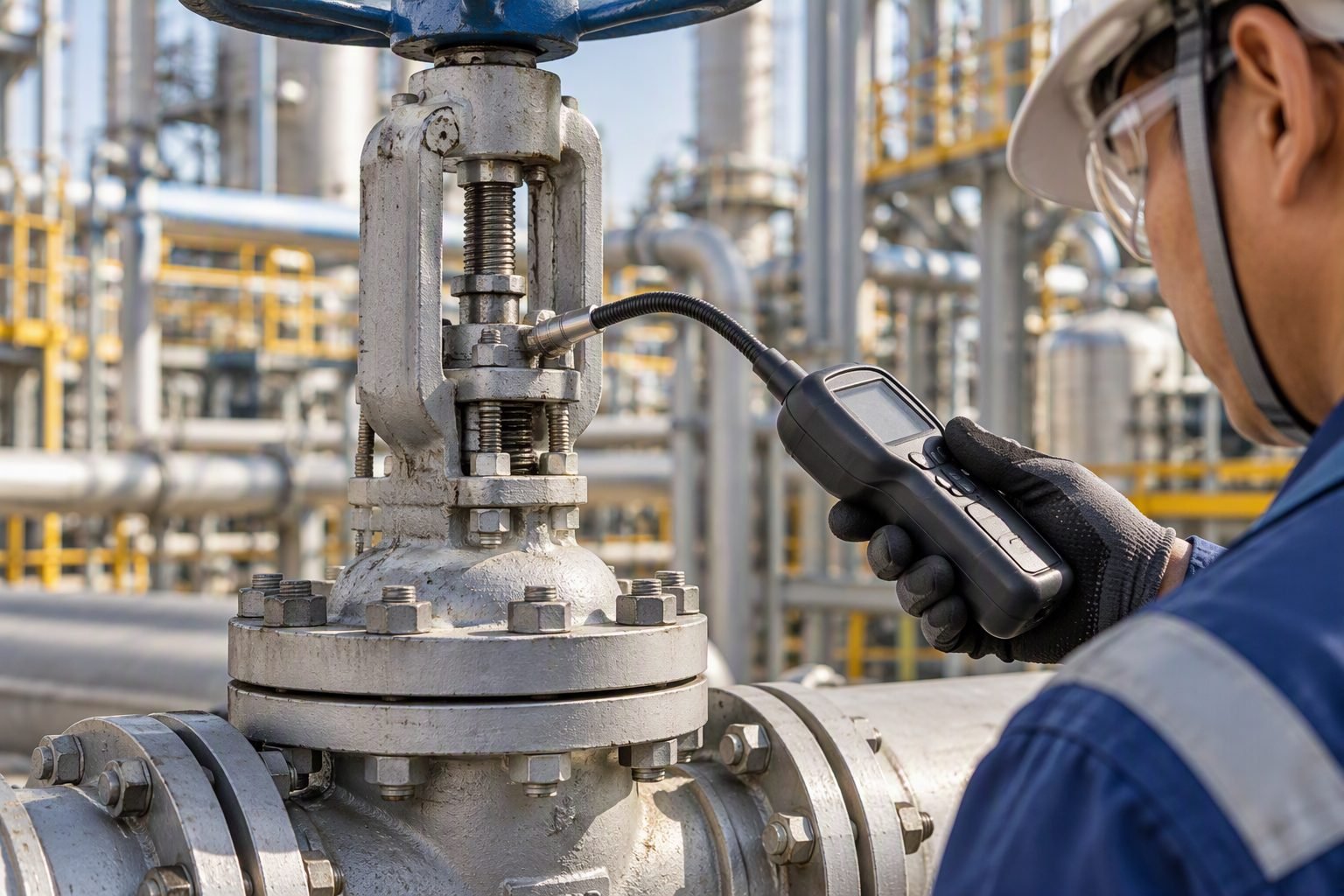
Gate Valve Seat Wire Drawing: Mechanics, Standards, and Prevention
In my twenty years of commissioning high-pressure hydrocarbon processing units and supercritical steam power plants, I have diagnosed countless catastrophic valve failures. When an operator throttles a standard wedge gate valve near its closed position, the differential pressure concentrates across an exceptionally narrow clearance. The resulting high-velocity jet stream behaves much like a high-pressure water cutter, initiating progressive metal removal known across the piping industry as wire drawing.
Understanding the fluid dynamics and metallurgical implications of wire drawing is essential for reliability engineers and piping designers. Left unchecked, this phenomenon destroys expensive cobalt-base alloy hardfacings, leads to fugitive emissions, and forces premature plant shutdowns for costly valve overhauls.
Key Engineering Takeaways
- Throttling services accelerate gate valve seat wire drawing due to high localized fluid velocities.
- Hardfacing materials like Stellite grade 6 mitigate surface wear but cannot prevent high-velocity erosive cutting.
- Compliance with API 598 pressure testing criteria is vital for detecting micro-leak paths.
- Proper valve selection dictates using globe or control valves for throttling instead of gate valves.
Mechanics of Gate Valve Seat Wire Drawing and Fluid Dynamics
Gate valves are strictly designed for on-off isolation duty rather than flow modulation. When a gate valve is cracked open to regulate fluid flow, the flow area contracts into an orifice-like geometry. According to Bernoulli’s principle and the continuity equation, fluid velocity through this restricted gap spikes dramatically. When liquid media carries suspended solid particulates or undergoes flashing and cavitation, the high-energy jet shears against the metal seat ring.
The fundamental mathematical expression governing flow velocity through a restrictive valve opening is derived from the differential pressure across the trim:
Where velocity (v) scales directly with the square root of the differential pressure drop (delta P) divided by fluid density (rho). In high-pressure steam or boiler feedwater applications, differential pressures can exceed 100 bar. As the fluid accelerates through a 0.5 mm micro-gap between the disc and seat, velocities often surpass sonic thresholds, creating destructive shear stresses that exceed the ultimate tensile strength of the base metal.
Critical Design Warning
Never use standard wedge gate valves for flow regulation or bypass control. Even minor throttling for short operational durations can initiate irreversible wire-drawing grooves that permanently ruin shut-off performance.
Metallurgical Degradation and Hardfacing Considerations
To combat abrasive wear, manufacturers apply cobalt-base or nickel-base hardfacings such as Stellite 6 to the seating surfaces of high-performance gate valves. While Stellite provides exceptional resistance to adhesive wear and galling at elevated temperatures up to 500 degrees Celsius, it remains vulnerable to high-velocity fluid droplet impact erosion and wire drawing.
When a microscopic leak path develops due to thermal cycling or pipeline stresses, fluid constantly scours the hardfacing layer. The micro-structure of the weld overlay experiences localized grain boundary attack. Over time, this creates a clean, narrow groove resembling a pencil mark or wire cut across the seating face. Once this channel breaches the seating band, the leakage rate accelerates exponentially, destroying the sealing integrity defined in ASTM standards for seat tightness.
Operational Diagnostics and Non-Destructive Testing
Detecting gate valve seat wire drawing before it leads to process shutdown requires disciplined maintenance practices. Plant engineers rely on acoustic emission monitoring and ASNT-compliant ultrasonic testing to identify turbulent flow noise across closed valves. Thermographic surveys also reveal abnormal downstream skin temperatures resulting from internal passing flows.
During scheduled turnaround overhauls, valves must undergo blue-checking of seats, liquid penetrant testing (PT) per ASME Section VIII, and helium leak testing to confirm seat closure performance in compliance with API 598 shell and seat test acceptance criteria.
Engineering Advantages of Gate Valve Designs
- Provides unobstructed, full-bore flow paths with virtually zero pressure drop when fully open.
- Bi-directional sealing capabilities simplify piping layout and installation orientation.
- Robust wedge designs handle high-temperature and high-pressure media effectively in isolation service.
- Minimal torque requirements for operation when equipped with proper gear operators or actuators.
- Long service life when strictly operated in fully open or fully closed positions.
Disadvantages and Failure Risks
- Extremely susceptible to wire drawing and seat erosion when used for throttling.
- Slow actuation speeds prevent rapid emergency shutdown actions.
- Prone to thermal binding if closed hot and allowed to cool down under pressure.
- Seating surfaces are difficult to lap or repair in-line without specialized machining tools.
- Requires substantial vertical clearance above the pipeline to accommodate the rising stem.
High-Pressure Steam Generation and Power Plants
Superheated steam systems in fossil fuel power stations operate at extreme pressures and temperatures exceeding 560 degrees Celsius. Gate valves installed on main steam headers must remain fully open during operation to prevent high-velocity steam cutting.
Improper warm-up procedures or cracked bypass valves frequently trigger wire drawing across boiler stop valve seats, requiring weld reclamation and precision machining.
Refinery Hydrocracker and Coker Unit Isolation
Petroleum refining units handle heavy hydrocarbon feeds laden with catalyst fines and corrosive sulfur compounds at high operating pressures. Gate valves in reactor effluent circuits are vulnerable to erosive wear if used improperly.
Process engineers specify specialized tungsten carbide hardfacings and strict interlocks to ensure gate valves never throttle erosive reactor feeds.
Long-Distance Pipeline Mainline Block Valves
Crude oil and natural gas transmission pipelines utilize large-diameter slab gate valves and expanding gate valves for mainline sectional isolation. These valves experience high flow velocities during pipeline pigging operations.
Maintaining complete valve actuation cycles ensures that debris does not lodge between the seat ring and gate, averting the micro-leakage that causes wire-drawing grooves.
Cryogenic Liquefied Natural Gas Storage Facilities
LNG transfer systems operate at minus 162 degrees Celsius, where metal contraction challenges tight shut-off tolerances. Gate valves in LNG rundown lines require extended bonnets and precision seat lapping.
Thermal shock during cool-down can distort valve bodies, creating microscopic clearance gaps where flashing boil-off gas initiates rapid wire-drawing erosion.
Gate Valve Wire Drawing Operational Parameters and Velocity Limits
Gate valve wire drawing is fundamentally governed by fluid velocity across micro-clearances, pressure drop ratios, and material hardness thresholds. When process media escapes past a partially open or degraded seating interface, the localized restriction accelerates fluid velocities into the supersonic or high-subsonic regime, initiating severe mechanical and chemical degradation. In my refinery and petrochemical plant design reviews, I frequently evaluate these operating thresholds against ASME B16.34 wall thickness and pressure class ratings to prevent catastrophic seat failure.
The engineering data table below outlines the critical operational boundaries, fluid characteristics, and material response indicators associated with high-velocity wire drawing phenomena. Reviewing these parameters ensures that valve selection matches the severe service demands dictated by high differential pressures.
| Parameter Category | Operating Condition / Limit | Associated Failure Mechanism | Governing Code / Standard |
|---|---|---|---|
| Critical Velocity Threshold | > 50 m/s (Liquid) / > Mach 0.3 (Gas) | Abrasive fluid jetting and localized cavitation pitting | API 598 / ASME B16.34 |
| Differential Pressure Ratio | Delta P > 1.5 MPa across tight clearance | Rapid micro-channel cutting and wire-draw grooving | ASME B16.34 |
| Seat Hardness Differential | Delta HRC < 5 between wedge and seat | Galling, localized micro-welding, and tearing | API 6D / API 600 |
| Stellite Overlay Thickness | < 1.5 mm deposited weld layer | Premature breakthrough of wear-resistant surface | ASME BPVC Section IX |
| Particle Entrainment | > 100 ppm solids larger than 50 microns | Accelerated abrasive impingement and groove widening | ISO 5208 |
Strict adherence to these operating parameters ensures that piping designers specify appropriate valve trim hardness and leakage classes, mitigating premature asset degradation in high-pressure steam and hydrocarbon service.
Technical Mapping & Specifications Matrix
Navigating industrial valve degradation requires a structured understanding of technical entities, physical standards, and specialized terminology. In my piping engineering practice, I rely on standardized nomenclature to communicate seat integrity requirements across multidisciplinary teams. This entity matrix maps out the core metallurgical, hydraulic, and mechanical components associated with gate valve seat wire drawing.
Use the comprehensive matrix below to correlate industry standards, material specifications, and physical phenomena when diagnosing valve passing issues or preparing procurement requisitions for severe service isolation valves.
| Entity / Component | Standard Reference | Primary Physical Parameter | Engineering Function |
|---|---|---|---|
| Gate Valve Assembly | API 600 / ASME B16.34 | Class 150 through Class 2500 | On-off fluid isolation in high-pressure piping systems |
| Hardfaced Seat Ring | AWS A5.13 (Cobalt-Base) | HRC 38 to HRC 45 hardness range | Resists abrasive wear and mechanical impact loads |
| Wedge Disc Interface | API 598 | Surface finish Ra < 0.8 micrometer | Forms primary bubble-tight seal against seat rings |
| Wire Drawing Phenomenon | ISO 5208 Leak Rate Rate D | Erosion velocity exceeding 100 m/s | Destructive localized metal removal from leakage path |
| Stellite Overlay | ASME Section IX | Cobalt alloy (Co-Cr-W) matrix | Provides superior high-temperature erosion resistance |
Proper integration of these entities during the engineering design phase ensures robust valve performance across aggressive industrial processing environments.
Gate Valve Seating and Wire Drawing Prevention Checklist
Preventing gate valve wire drawing requires rigorous field verification during fabrication, pre-commissioning, and routine plant turnarounds. Based on my extensive site commissioning experience, skipping quality checks on seat ring alignment and actuator stroke limits invariably leads to premature seat destruction. Piping engineers must enforce strict verification protocols before signing off on critical isolation valves.
The structured checklist below details the mandatory inspection checkpoints required to ensure gate valves remain leak-free and resistant to high-velocity erosion channels.
Field Quality Inspection Protocol for Gate Valve Seats
-
Verify Seat Ring Hardness Differential: Confirm that the wedge disc and body seat rings maintain a minimum hardness differential of 50 Brinell points or 5 HRC as specified in API 600 to prevent galling.
-
Check Hydrostatic Seat Leak Testing: Perform seat leakage testing strictly in accordance with API 598, ensuring zero visible leakage for resilient-seated or metal-seated valves during the holding duration.
-
Inspect Actuator Limit Switch Calibration: Ensure electric and pneumatic actuators are precisely calibrated so the gate fully wedges into the seat without backseat jamming or incomplete closure.
-
Evaluate Stellite Overlay Integrity: Utilize dye penetrant testing (ASME BPVC Section V) on hardfaced seating surfaces to detect any porosity, micro-cracks, or incomplete fusion zones.
-
Assess Process Fluid Velocity Profiles: Review line sizing and operating flow rates to confirm that fluid velocity near control bypasses and isolation valves remains safely below critical erosion limits.
-
Confirm Wedge Guidance Alignment: Check that body guiding ribs properly align the flexible or solid wedge disc to prevent uneven contact loading and localized clearance gaps.
Executing each checklist item during pre-commissioning inspections safeguards high-pressure assets against accelerated wire drawing failure.
Field Case Study: High-Pressure Steam Isolation Valve Failure Analysis
In my engineering consultancy practice, I investigated a severe seat wire drawing incident on a 12-inch Class 900 main steam isolation gate valve in a cogeneration power facility. The valve exhibited continuous thermal bypassing downstream and failed acoustic emission testing during routine plant operation. Disassembly revealed a deep, razor-sharp eroded groove cut across the Stellite seat ring, characteristic of high-velocity wire drawing.
Problem Statement
The 12-inch gate valve experienced severe localized metal loss on the downstream seat ring after only eight months of intermittent operation in superheated steam service.
- Operators frequently utilized the manual gate valve for partial flow throttling during warm-up sequences, violating design intent.
- High differential pressure across a 0.5 mm micro-gap accelerated steam velocity to supersonic levels, cutting a precise wire-drawing groove.
- Inadequate hardness matching between the wedge and seat ring accelerated mechanical wear and abrasive particle impingement.
- Pneumatic actuator travel stops drifted by 4 millimeters, preventing full mechanical wedging against the body seat angle.
Solution and Outcome
The damaged valve was completely refurbished, retrofitted with hardened trim, and paired with an automated warm-up bypass line to eliminate throttling across the primary gate.
- Replaced standard seating with Stellite 6 alloy weld overlay, achieving a Brinell hardness exceeding 400 HB across both mating faces.
- Installed a dedicated 2-inch warm-up control valve with tungsten carbide trim to handle high differential pressure during startup phases.
- Recalibrated and locked actuator limit switches in strict accordance with API 600 seating requirements.
- Conducted post-repair high-pressure seat testing per API 598, verifying zero leakage across 15 minutes of hold time.
This remediation eliminated recurring wire drawing damage, extending valve operational life beyond five years of continuous service without further thermal bypassing.
Frequently Asked Engineering Questions
What exactly causes wire drawing damage in industrial gate valves?
- Excessive pressure differentials across the sealing wedges.
- Entrained abrasive particulates acting as a liquid-solid cutting medium.
- Subcritical flashing or localized cavitation within the micro-gap.
- Softened seating alloys failing to resist mechanical shear forces.
How does ASME B16.34 govern gate valve seat integrity limits?
- Minimum body wall thickness accounts for potential erosion corrosion allowances.
- Selected valve classes match maximum allowable working pressure limits without micro-deflection.
- Shell and seat hydrostatic tests verify zero initial bypass before high-pressure service deployment.
Why are gate valves unsuitable for flow throttling applications?
- Rapid mechanical wear and galling on wedge guide faces.
- Unpredictable flow characteristics due to non-linear percentage changes.
- Accelerated wire-drawing groove formation across the parallel sealing rings.
- Premature seat destruction requiring costly inline machining or replacement.
What field detection methods identify early-stage wire drawing?
- Ultrasonic acoustic emission testing to detect high-frequency turbulence leakage paths.
- Downstream skin-temperature thermography indicating thermal energy loss past closed valves.
- Helium leak testing or block-and-bleed pressure decay verifications.
- Borescopic visual examination of removed seat rings to map micro-groove depth profiles.
Which hardfacing alloys offer maximum resistance to seat erosion?
- Cobalt-based Stellite alloys (Stellite 6 or 21) providing exceptional anti-galling and erosion resistance.
- Nickel-chromium-boron self-fluxing alloys for corrosive chemical processing units.
- Tungsten carbide thermal spray coatings for severe solid-particle slurry services.
- Matching base metal hardness differentials to prevent adhesive wear during seating cycles.
Field Recommendation
In my professional piping design and maintenance practice, mitigating gate valve seat wire drawing demands rigorous engineering judgment right from the specification phase. When designing high-pressure liquid or steam isolation loops, I advise making specific, proactive decisions rather than relying on standard off-the-shelf procurement packages.
- If your piping system involves differential pressures exceeding 1.5 MPa with flashing potential, choose wedge gate valves with cobalt-based Stellite 6 hardfacing overlays because untreated austenitic stainless steel seats will erode within months of minor passing.
- If operators are tempted to use gate valves for flow control in utility headers, choose to substitute globe or characterized V-ball valves immediately, because throttling a gate valve inevitably creates the micro-gap required for destructive wire drawing.
- If routine acoustic monitoring indicates minor downstream temperature anomalies across a critical isolation valve, choose to schedule an immediate internal inspection and lapping procedure rather than waiting for a planned turnaround, preventing complete seat ring destruction.
- If handling abrasive slurry services with suspended catalyst fines, choose tungsten carbide thermal spray coatings applied via high-velocity oxy-fuel processes for all seating surfaces to resist particle-impact cutting.
Complete Course on
Piping Engineering
Check Now
Key Features
- 125+ Hours Content
- 500+ Recorded Lectures
- 20+ Years Exp.
- Lifetime Access
Coverage
- Codes & Standards
- Layouts & Design
- Material Eng.
- Stress Analysis
