Table of Contents
Understanding Gasket m and y Factors in Flange Design
In my 20 years of troubleshooting high-pressure piping systems, I have seen countless flange joints weep, hiss, or catastrophically blow out because a designer treated gasket selection as an afterthought. Many engineers blindly copy values from old spreadsheets without understanding how these factors dictate the mechanical integrity of a bolted joint. When you are dealing with lethal service or high-temperature hydrocarbons, relying on incorrect gasket parameters is a recipe for disaster.
The ASME Boiler and Pressure Vessel Code (BPVC) provides a structured methodology for flange design, but it relies heavily on the user selecting the correct gasket constants. If you underestimate these values, your flange will lack the structural rigidity and bolt load required to maintain a seal under pressure. Conversely, overestimating them can lead to crushed gaskets, bent flanges, or sheared bolts. Let me walk you through how these factors actually behave under real-world bolt-up and operating conditions.
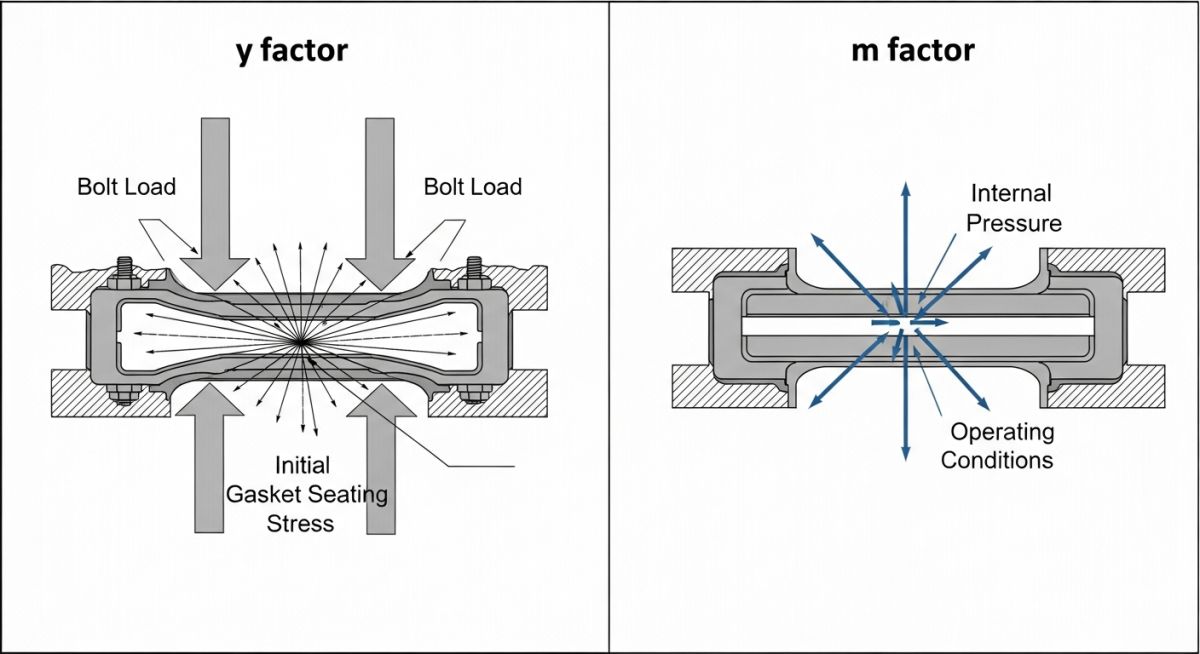
- The y factor is an ambient-temperature seating stress that must be overcome before any internal pressure is applied.
- The m factor is a dynamic multiplier that ensures the residual stress on the gasket remains higher than the process pressure during operation.
- ASME Section VIII Appendix 2 values are non-mandatory guidelines; modern high-performance gaskets often require manufacturer-specific testing data.
- Flange rotation and thermal relaxation are not directly accounted for by m and y factors, requiring supplementary analysis via ASME PCC-1 guidelines.
- Using incorrect factors directly leads to either gasket crushing or joint separation under thermal cycles.
Demystifying Gasket m and y Factors in ASME
To design a flange under ASME Section VIII Division 1, we must analyze two distinct design conditions: the gasket seating condition and the operating condition. Each of these conditions is governed by one of our core gasket factors.
The Seating Factor (y) Explained
The y factor is defined as the minimum design joint-contact seating stress in pounds per square inch (psi) or Megapascals (MPa). This factor represents the initial compressive stress required to deform the gasket material into the microscopic imperfections of the flange faces. This deformation is what creates the initial physical barrier against fluid bypass.
The calculation for the minimum bolt load required for gasket seating (Wm2) is expressed as:
Where b is the effective gasket sealing width, and G is the gasket load reaction diameter. Note that this condition occurs at ambient temperature and atmospheric pressure, meaning the only force acting on the joint is the mechanical clamp of the bolts.
The Maintenance Factor (m) Explained
Once the system is pressurized, the physical dynamics change. The internal fluid pressure exerts a hydrostatic end force that tries to push the flanges apart. This action unloads the gasket. To prevent the joint from leaking, we must maintain a residual compressive stress on the gasket that is higher than the internal pressure.
This is where the m factor (gasket factor) comes into play. It is a dimensionless ratio that defines how many times the internal pressure the residual gasket stress must be. The minimum bolt load required for the operating condition (Wm1) is calculated as:
Where P is the internal design pressure. The first term represents the hydrostatic end force, while the second term represents the joint contact force required to keep the gasket sealed under pressure.
In my field audits, I often find engineers using the default values from ASME Section VIII Table 2-5.1 without consulting the actual gasket manufacturer. The values in Table 2-5.1 are non-mandatory and were established decades ago. Modern materials like structured PTFE or high-density flexible graphite often exhibit vastly different sealing characteristics. Relying on outdated default values can lead to under-bolted joints that leak during thermal transients.
Limitations of the Classical m and y Method
While the m and y method has been the backbone of pressure vessel design for generations, it is important to recognize its limitations. This method assumes rigid flanges and does not account for flange rotation, bolt relaxation, or thermal expansion differentials. For critical, high-temperature, or high-pressure applications, I highly recommend performing a supplementary analysis using the newer PVRC (Pressure Vessel Research Council) constants (Gb, a, and Gs) which focus on tightness-based design criteria.
Standard Gasket m and y Factors Reference
Below is a reference table compiled from standard industry values and ASME guidelines. It highlights how the physical composition of the gasket dictates its design factors. Note how harder metallic gaskets require significantly higher seating stresses (y) compared to soft elastomers.
| Gasket Type | Material / Description | m Factor | y Factor (psi) | y Factor (MPa) |
|---|---|---|---|---|
| Elastomer (Soft) | Rubber without fabric (below 75 Shore A) | 0.50 | 0 | 0 |
| Compressed Fiber | Non-asbestos with elastomer binder | 2.00 | 1,600 | 11.0 |
| Spiral Wound | Stainless Steel with Flexible Graphite filler | 3.00 | 10,000 | 68.9 |
| Spiral Wound | Stainless Steel with PTFE filler | 3.00 | 10,000 | 68.9 |
| Corrugated Metal | Soft Aluminum or Copper jacketed | 2.75 | 3,700 | 25.5 |
| Ring Joint (RTJ) | Octagonal or Oval Soft Carbon Steel | 5.50 | 18,000 | 124.1 |
To bridge the gap between theoretical design and field execution, this matrix maps the core technical entities, physical parameters, and their corresponding code references.
| Parameter / Entity | Symbol | Physical Unit | ASME Reference | Engineering Significance |
|---|---|---|---|---|
| Gasket Factor | m | Dimensionless | Appendix 2, Table 2-5.1 | Determines operating bolt load to prevent separation under pressure. |
| Gasket Seating Stress | y | psi / MPa | Appendix 2, Table 2-5.1 | Defines initial stress required to flow gasket into flange face. |
| Basic Gasket Width | b0 | inches / mm | Table 2-5.2 | Raw contact width based on physical geometry of the gasket. |
| Effective Sealing Width | b | inches / mm | Table 2-5.2 | Calculated width used in load equations to account for flange rotation. |
| Load Reaction Diameter | G | inches / mm | Appendix 2-3 | The location where the gasket load is assumed to act on the flange. |
Site Verification Checklist for Bolted Joints
Even the most precise calculations on paper will fail if the field execution is sloppy. In my experience, over 80% of flange leaks are caused by poor installation practices rather than design errors. Use this checklist on-site to verify that your bolted joints are assembled to match the design intent.
-
Verify Gasket Material and Dimensions: Cross-reference the physical gasket markings with the design datasheet. Ensure the m and y factors used in the calculations match the specific brand and model of the gasket being installed.
-
Inspect Flange Face Finish: Ensure the flange surface roughness matches the gasket requirements. For spiral wound gaskets, verify a serrated concentric or spiral finish between 125 and 250 micro-inches AARH.
-
Check Flange Alignment: Verify that flange faces are parallel within 0.010 inches per inch of flange diameter, and bolt holes align within 1/8 inch maximum offset to prevent asymmetric loading.
-
Lubricate Bolts Properly: Apply a high-quality anti-seize lubricant with a known torque coefficient (K-factor) to the bolt threads and nut bearing faces. Unlubricated bolts can lose up to 50% of torque energy to friction.
-
Execute Multi-Stage Torque Pattern: Tighten bolts in a star pattern using increments of 30%, 60%, and 100% of target torque, followed by a final rotational pass to ensure uniform gasket compression.
-
Perform Hot Torque (If Applicable): For high-temperature systems, perform a hot torque pass once the system reaches operating temperature to compensate for thermal relaxation of the bolts and gasket.
Field Case Study: Real-World Application
During a refinery turnaround, a 12-inch Class 300 superheated steam line operating at 600 psi and 650°F experienced chronic, repetitive leakage at a critical flange joint. The original design calculations had utilized the standard ASME Table 2-5.1 default values for a spiral wound gasket (m=3.00, y=10,000 psi). Because the default values underestimated the actual seating stress required for the high-density graphite-filled gasket in service, the bolts were under-torqued. Under thermal cycling, the joint relaxed, the residual stress dropped below the operating threshold, and steam cut through the gasket face.
I stepped in to perform a root cause analysis. We discarded the default ASME values and obtained the actual, tested gasket m and y factors from the manufacturer (m=4.25, y=12,500 psi). Using these updated parameters, we recalculated the required bolt load and upgraded the stud bolts from standard grade to ASTM A193 Grade B7. We then applied a controlled torque profile using hydraulic tensioners. The joint was brought back online and has operated for 36 months of continuous thermal cycling without a single micro-leak.
This case highlights why relying on generic code tables can be dangerous. Always verify your design parameters with the actual manufacturer of the sealing element to ensure your calculations reflect physical reality.
Frequently Asked Engineering Questions
Are the m and y factors in ASME Section VIII Table 2-5.1 mandatory?
How does temperature affect the gasket m and y factors?
What is the difference between basic gasket width (b0) and effective gasket width (b)?
Can a gasket have a y factor of zero?
Why does a higher m factor require larger bolts?
How do PVRC constants differ from ASME m and y factors?
Complete Course on
Piping Engineering
Check Now
Key Features
- 125+ Hours Content
- 500+ Recorded Lectures
- 20+ Years Exp.
- Lifetime Access
Coverage
- Codes & Standards
- Layouts & Design
- Material Eng.
- Stress Analysis

📚 Recommended Resources: gasket m and y factors
Read these Guides
🎓 Advanced Training
🎥 Watch Tutorials

Related posts:
![An engineer performing an API 579 fitness for service assessment on an industrial pressure vessel.]()
How to Perform API 579 Fitness for Service Assessment
![PASS/START-PROF 4.86 pipe stress analysis software interface displaying a 3D piping model.]()
PASS/START-PROF 4.86 Released: Discover the New Pipe Stress Analysis Capabilities
![ASME certification mark stamped on an industrial pressure vessel nameplate]()
What is ASME Certification? Procedure and Mark Explained
![Professional technician inserting a high-pressure hydro jetting nozzle into a sewer pipe cleanout.]()
What is Hydro Jetting and How Does It Work?
![Side-by-side comparison diagram of stub-in and stub-on piping branch connections.]()
Stub-in vs Stub-on Piping Connections: Engineering Design Guide
![A restriction orifice plate installed between pipe flanges in an industrial piping system.]()
What is a Restriction Orifice? Working, Types, and Sizing Guide