What is a Flange Coupling? Advantages, Types, Working, Uses
In my 20 years of field engineering, I have seen many power transmission setups fail simply because of poor coupling selection. When you are dealing with high-torque, heavy-duty machinery, you cannot afford any slip or misalignment. That is where the flange coupling comes in. It is the workhorse of heavy industrial drives, providing a rock-solid, rigid connection that ensures zero relative motion between shafts.
Throughout my career on refinery and chemical plant sites, I have relied on these robust components to connect large pumps, compressors, and marine propulsion shafts. When designed and installed correctly, they offer unmatched torque transmission efficiency. Let us dive deep into how these couplings work, their distinct types, and how to select the right one for your specific engineering application.
- Rigid flange couplings provide zero-backlash torque transmission for perfectly aligned shafts.
- Protected designs feature a protective circumferential lip to shield personnel from rotating bolt heads.
- Marine flange couplings utilize tapered bolts and integrated shaft flanges for extreme propulsion loads.
- Precise alignment and correct bolt pre-tensioning are critical to prevent catastrophic shear failures.
What is a Flange Coupling?
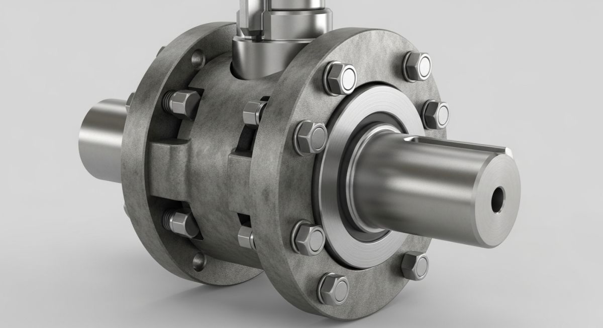
A flange coupling is a rigid type of coupling that brings two shafts together coaxially. It consists of two separate flanges—one keyed to the driving shaft and the other to the driven shaft. These flanges are then bolted together using a circle of bolts to complete the drive connection. Because they are rigid, they do not accommodate shaft misalignment. Any attempt to use them on misaligned shafts will induce severe bending moments, leading to premature bearing failure or shaft fatigue.
Working of a Flange Coupling
The working principle is straightforward yet highly effective. Power is transferred from the driving shaft to its flange hub via a keyway connection. Once the driving flange rotates, the torque is transmitted to the driven flange through the bolted joint. This transmission occurs in two ways: through the shear resistance of the tightly fitted bolts, and through the friction generated between the highly compressed mating faces of the two flanges.
Key Components of the Assembly
To understand the system fully, we must break down its primary components:
- Flange Hubs: Typically made of cast iron or cast steel, these are bored to match the shaft diameters and feature a radial flange face.
- Keys and Keyways: Parallel or tapered keys designed to transmit torque from the shaft to the hub, complying with ASME B17.1.
- Coupling Bolts: High-tensile fasteners positioned in a precise pitch circle. In high-speed applications, these are fitted bolts that fill the holes completely.
- Spigot and Recess (Register): A male projection on one flange face that fits into a female recess on the mating flange to ensure perfect concentric alignment.
Never install a rigid flange coupling without verifying shaft alignment using a dial indicator or laser alignment tool. Even a minor parallel misalignment of more than 0.05 mm will generate massive cyclic stresses, destroying your bearings and risking a catastrophic shaft snap.
Engineering Design Calculations
When designing a flange coupling, we must calculate the shear stresses in the keys, bolts, and the flange itself. Here are the fundamental design formulas used in my practice:
T = (pi / 16) * allowable shear stress of shaft * (shaft diameter cubed)
T = number of bolts * (pi / 4) * (bolt diameter squared) * tau_b * (pitch circle diameter / 2)
T = width of key * length of key * tau_k * (shaft diameter / 2)
T = pi * (hub diameter squared) * thickness of flange * tau_f * 0.5
Types of Flange Couplings
Depending on safety requirements and operating environments, we categorize these couplings into three primary types:
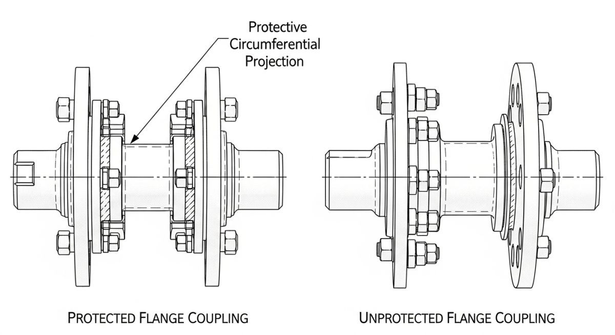
- Protected Flange Coupling: Features an outer shroud or protective circumferential lip that covers the projecting bolt heads and nuts. This prevents operators’ clothing from getting caught in the rotating assembly.
- Unprotected Flange Coupling: Lacks the protective shroud, leaving bolt heads exposed. These are only used inside enclosed machine guards or low-speed, low-risk areas.
- Marine Flange Coupling: Designed for heavy marine propulsion shafts. The flanges are forged integrally with the shafts, and tapered bolts are used instead of standard keys to handle extreme thrust and torque.
The table below outlines standard dimensions and torque capacities for cast iron flange couplings based on shaft diameters, complying with standard industrial practices and ISO 1940 balancing guidelines.
| Shaft Diameter (mm) | Hub Diameter (mm) | Pitch Circle Dia (mm) | Number of Bolts | Bolt Size (Metric) | Max Torque (Nm) |
|---|---|---|---|---|---|
| 25 | 50 | 100 | 3 | M8 | 350 |
| 40 | 80 | 140 | 4 | M10 | 950 |
| 60 | 120 | 190 | 4 | M12 | 2,400 |
| 80 | 160 | 240 | 6 | M16 | 5,800 |
| 100 | 200 | 300 | 6 | M20 | 11,500 |
This matrix maps the core components of a flange coupling assembly to their material specifications, key design parameters, and relevant international standards.
| Component / Entity | Material Specification | Key Parameter | Applicable Standard |
|---|---|---|---|
| Flange Hubs | Grey Cast Iron (Grade 25/35) or Cast Steel | Tensile Strength, Hub Thickness | ASTM A48 / A216 |
| Coupling Bolts | High-Tensile Carbon Steel (Grade 8.8 / 10.9) | Shear Stress, Pre-torque Tension | ISO 898-1 |
| Sunk Keys | Medium Carbon Steel (C45 / C50) | Shear & Crushing Resistance | ASME B17.1 |
| Spigot Alignment | Machined Interface | Concentricity Tolerance (H7/g6) | ISO 286 |
Site Verification Checklist for Flange Coupling Installation
In my experience, more than 70% of early coupling failures are caused by poor installation practices. Use this checklist on-site to verify that your rigid flange coupling is set up for long-term reliability.
-
Shaft Alignment Verification:
Measure parallel and angular alignment using a dial indicator or laser tool. Ensure parallel deviation is under 0.03 mm and angular deviation is under 0.05 degrees. -
Keyway and Key Fit:
Check that the key fits snugly in both the shaft and hub keyways without excessive lateral play. Refer to ASME B17.1. -
Bolt Torque Calibration:
Tighten all coupling bolts in a star pattern using a calibrated torque wrench. Ensure torque values match the manufacturer’s specification sheet. -
Spigot-Recess Engagement:
Confirm that the male spigot fits cleanly into the female recess without forcing or binding, ensuring concentricity. -
Safety Guard Installation:
For unprotected couplings, verify that a robust, non-rotating safety guard is securely bolted over the entire rotating assembly.
Field Case Study: Real-World Application
At a municipal water treatment plant, a 150 kW centrifugal pump driven by an electric motor suffered from recurrent coupling bolt shear failures. Every three to four months, the bolts on the unprotected flange coupling would shear off, causing unplanned shutdowns. The maintenance team had been replacing the bolts with standard hardware-grade fasteners, but the issue persisted. I was called in to analyze the system.
Upon inspection, I discovered two major issues: a parallel shaft misalignment of 0.18 mm (well above the 0.03 mm limit) and the use of low-grade bolts. We resolved this by performing a precision laser alignment to bring the shafts within 0.02 mm. Next, we replaced the standard bolts with high-tensile Grade 8.8 fitted bolts, reaming the flange holes to ensure a tight body-bound fit. Finally, we upgraded the assembly to a protected flange coupling to improve site safety.
The results were immediate. Vibration levels dropped from 7.2 mm/s to 1.1 mm/s, complying with ISO 10816. The pump has now run for over three years without a single bolt failure.
My direct recommendation for any high-torque rigid coupling setup is to always use body-bound, high-tensile fitted bolts and verify alignment using laser tools. Never rely on standard clearance bolts to transmit torque through shear.
Frequently Asked Engineering Questions
What is the main difference between a protected and unprotected flange coupling?
Can a flange coupling accommodate shaft misalignment?
Why are marine flange couplings designed without keys?
What materials are typically used to manufacture flange couplings?
How do you calculate the number of bolts required for a flange coupling?
What is the purpose of the spigot and recess on the flange faces?
Complete Course on
Piping Engineering
Check Now
Key Features
- 125+ Hours Content
- 500+ Recorded Lectures
- 20+ Years Exp.
- Lifetime Access
Coverage
- Codes & Standards
- Layouts & Design
- Material Eng.
- Stress Analysis



