Fire Hydrant System Design: Types, Working, and NFPA Standards 2026
Imagine a high-stakes emergency where every second counts, but when the fire brigade connects to the local network, the pressure fails or the valve is frozen solid. This nightmare scenario is usually the result of a fundamental failure in Fire Hydrant System Design.
Properly engineered fire protection is more than just placing red pillars on a sidewalk; it is a complex calculation of hydraulic flow, material science, and climate-specific mechanics. In this 2026 guide, we break down the critical engineering standards that ensure life-saving water is available exactly when the heat is on.
Key Takeaways
- Understanding the environmental triggers for selecting Wet Barrel vs. Dry Barrel configurations.
- Mastering the 2026 NFPA 291 color-coding standards for instantaneous flow rate identification.
- Integrating hydraulic calculations with NFPA 24 for robust distribution networks.
What is a Fire Hydrant System Design?
A Fire Hydrant System Design is an active fire protection measure consisting of a network of pipes, valves, and connection points designed to provide a high-pressure water supply for firefighting. It utilizes either wet or dry barrel hydrants, governed by NFPA 24 and NFPA 291 standards to ensure specific flow rates and frost protection.
Founder’s Insight
“In over two decades of industrial MEP planning, I have seen that the most common error in Fire Hydrant System Design is neglecting the ‘last mile’ of hydraulic friction loss. A hydrant is only as good as the pipe diameter feeding it—don’t compromise on your mains.”
— Atul Singla
Complete Course on
Piping Engineering
Check Now
Key Features
- 125+ Hours Content
- 500+ Recorded Lectures
- 20+ Years Exp.
- Lifetime Access
Coverage
- Codes & Standards
- Layouts & Design
- Material Eng.
- Stress Analysis
Knowledge Check: Fire Hydrant Engineering
Validate your expertise in Fire Hydrant System Design standards for 2026.
Question 1 of 5
In a Dry-Barrel Fire Hydrant System Design, where is the main valve located to prevent freezing?
Correct! In dry-barrel designs, the valve is underground below the frost line. When closed, the barrel drains completely via a drain hole to prevent ice expansion damage.
What is a Fire Hydrant System Design and Its Purpose?
A Fire Hydrant System Design serves as the backbone of active fire protection for municipal, industrial, and residential sectors. Its primary purpose is to provide a readily accessible, high-volume water source for firefighters to suppress localized blazes or prevent the spread of massive conflagrations. Unlike standalone extinguishers, a hydrant system is integrated directly into a water distribution network, ensuring a continuous supply that can last for hours.
The engineering behind a Fire Hydrant System Design must account for peak hourly demand and fire flow requirements simultaneously. In 2026, modern systems are increasingly designed using hydraulic modeling software to ensure that residual pressure remains above 20 psi (1.4 bar) during maximum discharge, as mandated by the NFPA 24 Standard. This ensures that the water mains do not collapse due to vacuum pressure and prevents the contamination of the potable water supply.
The Mechanics: How a Fire Hydrant Works
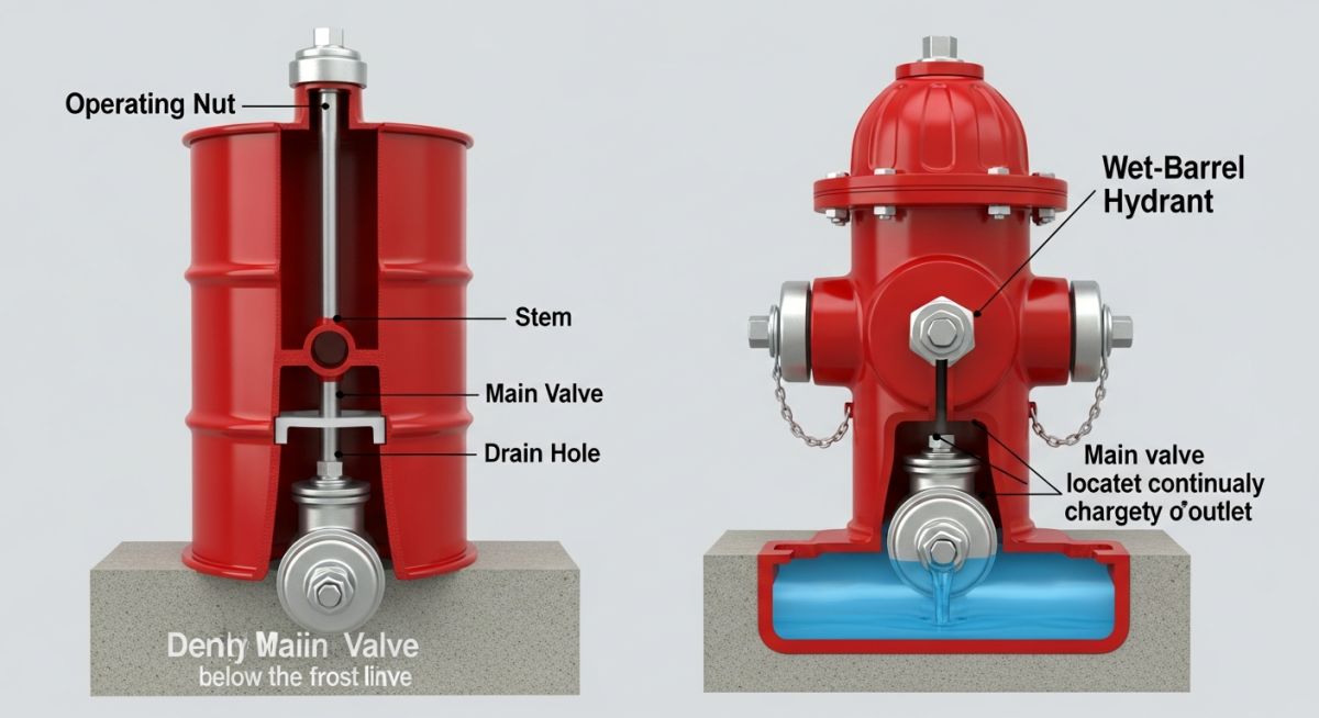
The fundamental working principle of a Fire Hydrant System Design involves the mechanical diversion of pressurized water from an underground main to an above-ground outlet. When a firefighter rotates the operating nut located at the top of the hydrant, it moves an internal valve stem. In a dry-barrel system, this action pushes the main valve downward, allowing water to flow from the lateral pipe into the hydrant barrel and out through the pumper or hose nozzles.
A critical mechanical feature in modern 2026 designs is the “Traffic Flange” or break-away coupling. If a vehicle impacts the hydrant, the flange snaps, allowing the upper barrel to fall away without damaging the main valve located deep underground. This prevents the classic “geyser” effect seen in older cinema and keeps the water distribution network intact.
Wet vs Dry: Selecting a Fire Hydrant System Design for Your Climate
Choosing between a wet-barrel and a dry-barrel Fire Hydrant System Design is primarily a geographical and environmental decision. The choice dictates the longevity of the infrastructure and the reliability of the fire response during extreme weather events.
In warmer climates where the ground never freezes, a Wet-Barrel Hydrant is preferred. In this design, the entire barrel is filled with pressurized water at all times. Each outlet has its own independent valve, allowing multiple hoses to be connected or disconnected without shutting down the entire hydrant. Conversely, in regions prone to sub-zero temperatures, a Dry-Barrel Hydrant is mandatory. The water is held below the frost line by a main valve, and the barrel remains empty (dry) when not in use. A drain valve at the base opens when the main valve is closed, allowing any residual water to seep into the surrounding gravel bed, preventing ice-related ruptures.
Critical Components of a Fire Hydrant System Design
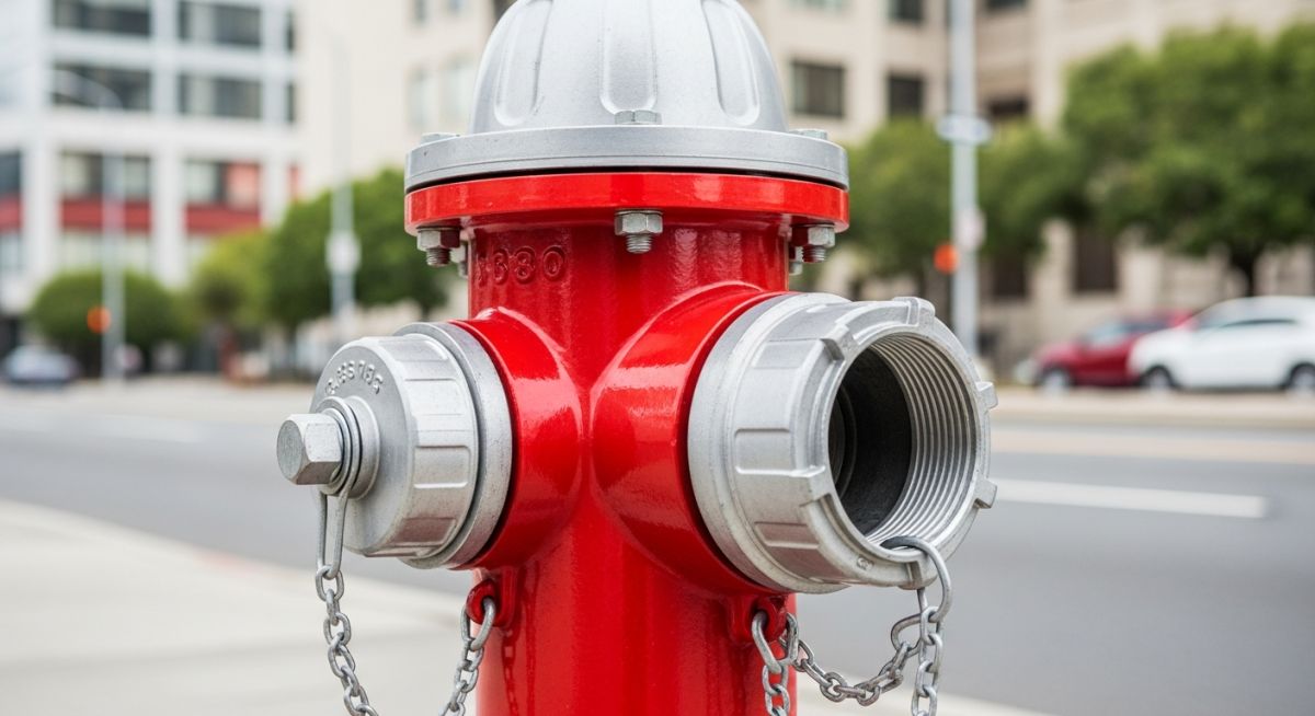
An optimized Fire Hydrant System Design relies on high-grade metallurgical components designed to withstand 250 psi or higher working pressures. The primary assembly consists of the Bonnet, which houses the Operating Nut and lubricant reservoir, and the Upper Barrel, typically cast from ductile iron for impact resistance.
In 2026, the Main Valve assembly remains the most critical point of failure. Modern designs utilize resilient-seated valves that provide a bubble-tight shut-off. Furthermore, the Pumper Nozzle (typically 4.5 inches) and Hose Nozzles (2.5 inches) must be threaded to local fire department specifications or the NFPA 1963 standard to ensure rapid coupling during emergencies.
2026 NFPA Color Coding for Fire Hydrant System Design
The color-coding of a Fire Hydrant System Design is not aesthetic; it is a vital communication tool for incident commanders. The NFPA 291 standard dictates specific colors for the hydrant caps and bonnets to indicate the available flow capacity at 20 psi residual pressure. This allows firefighters to instantly determine if a hydrant can support a single hose line or an entire pumper truck’s demand.
| Class | Color (Cap/Bonnet) | Flow Capacity (GPM) | Flow Capacity (L/min) |
|---|---|---|---|
| Class AA | Light Blue | 1,500 or Greater | 5,680 or Greater |
| Class A | Green | 1,000 – 1,499 | 3,785 – 5,675 |
| Class B | Orange | 500 – 999 | 1,900 – 3,780 |
| Class C | Red | Less than 500 | Less than 1,900 |
Codes and Standards: Ensuring Fire Hydrant System Design Compliance
Engineering compliance for a Fire Hydrant System Design is governed by several international and local authorities. The NFPA 291 Recommended Practice provides the framework for flow testing and marking, while the AWWA C502 standard (American Water Works Association) specifies the manufacturing requirements for dry-barrel fire hydrants.
In industrial settings, FM Global (Factory Mutual) data sheets often override municipal codes, requiring shorter spacing between hydrants (typically 250-300 feet) to ensure that two streams of water can reach any part of a building footprint. Adherence to these standards in 2026 is critical for insurance underwriting and life safety audits.
Fire Hydrant Flow & Pressure Calculator
Calculate the theoretical flow rate and determine the Fire Hydrant System Design class (NFPA 291).
Standard: 2.5″ or 4.5″ (Pumper)
Measured during discharge
Estimated Flow
0 GPM
NFPA 291 Class
N/A
This calculation provides the theoretical flow rate at the tested pressure. To determine the Fire Hydrant System Design rating, refer to residual pressure at 20 PSI.
Expert Case Study: Fire Hydrant System Design in High-Rise Applications
Project: Metro-Hub Vertical City (2026)
Industrial Fire Protection Audit
The Challenge
A 45-story mixed-use development required a Fire Hydrant System Design capable of delivering 2,500 GPM at the highest remote standpipe while maintaining a 60 PSI residual pressure. Initial municipal water pressure was insufficient for the upper zones.
The Solution
Engineers implemented a “Zoned Gravity-Feed” strategy. By installing intermediate 50,000-gallon break tanks and secondary fire pumps, the Fire Hydrant System Design bypassed traditional pressure limitations, ensuring NFPA 14 compliance.
Key Technical Results:
- 2,850 Actual GPM Flow
- 6″ Riser Diameter
- Class AA System Rating
EPCLand YouTube Channel
2,500+ Videos • Daily Updates
Expert Insights: Lessons from 20 years in the field
-
Friction Loss Oversight: Many engineers fail to account for the internal tuberculation in aging ductile iron pipes. For any Fire Hydrant System Design involving existing brownfield infrastructure, always use a conservative Hazen-Williams coefficient (C-factor of 100 or less) to ensure hydraulic reliability.
-
Thrust Block Integrity: In high-pressure municipal loops, the mechanical joint at the base of the hydrant is a critical stress point. Ensure Fire Hydrant System Design drawings specify concrete thrust blocks or restrained joints to prevent separation during the “water hammer” effect when valves are closed rapidly.
-
Drainage Pathing: For dry-barrel installations, the quality of the stone drainage bed is paramount. If the soil has high clay content, the barrel won’t drain, leading to winter freeze-ups. Always specify at least 1/3 cubic yard of clean, 1-inch crushed stone at the base.
Authority FAQ: Fire Hydrant System Design
What is the standard spacing for a Fire Hydrant System Design in residential areas?
Does a Fire Hydrant System Design require a dedicated water tank?
What is the “residual pressure” requirement for hydrants?
Why did my hydrant fail the annual flow test despite having high static pressure?
Can I use a wet-barrel hydrant in a climate that only freezes occasionally?
How does the “Traffic Flange” actually save money in municipal maintenance?

Related posts:
![High-grade industrial Wing Nut Types and Applications for mechanical assemblies.]()
Wing Nut Types and Applications: The 2026 Engineering Guide
![Industrial Monorail Crane Systems installed in a modern manufacturing plant 2026.]()
Monorail Crane Systems: Design, Types & 2026 Standards Guide
![Lead engineer performing a Factory Acceptance Test FAT on an industrial skid system 2026]()
Factory Acceptance Test FAT: The 2026 Engineering Guide to Zero-Defect Delivery
![Professional engineering workspace showing a Basis of Design document layout for a 2026 project.]()
Basis of Design: How to Write a BOD for Engineering Projects in 2026
![Industrial Flare Knockout Drum Sizing and installation in a refinery relief system.]()
Flare Knockout Drum Sizing: Design & API 521 Standards (2026 Guide)
![Advanced Reboiler Control Systems in a modern petrochemical refinery 2026.]()
Reboiler Control Systems: Engineering Guide to Precision Control 2026


