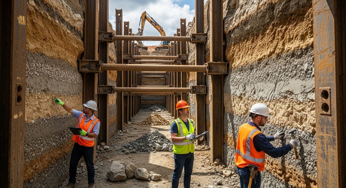
Managing Excavation Hazards and Control Measures for Site Safety
In my 20 years of managing heavy civil and piping projects, I have stood at the edge of trenches that looked perfectly stable, only to watch them shear and collapse without warning. Soil is a deceptive material; a single cubic yard can weigh as much as a small car, leaving zero room for error. This guide breaks down the physics of soil mechanics, structural shoring design, and the field-tested protocols required to keep your crew safe.
Key Engineering Takeaways
- Soil classification directly dictates the selection of protective systems.
- Hydrostatic pressure is a primary driver of sudden trench wall failure.
- Daily competent person inspections are non-negotiable before any worker enters an excavation.
Understanding Excavation Hazards and Control Measures
To design effective protective systems, we must first understand the forces at play. Soil is held together by internal friction and cohesion. When we dig a trench, we remove the lateral support that keeps the surrounding soil in place. This creates a state of unbalanced stress, causing the soil to move downward and inward toward the excavation.
Calculating Lateral Earth Pressure
The lateral pressure exerted by the soil against a shoring system is calculated using Rankine’s theory of active earth pressure. For a cohesive-less soil, the active earth pressure coefficient (Ka) is determined by the angle of internal friction (phi):
Once Ka is established, the total active lateral force (Pa) per unit length of the wall for a trench of depth (H) and soil unit weight (gamma) is calculated as:
For example, if we have a trench depth of 10 feet in a Type B sandy loam with a unit weight of 120 pounds per cubic foot and an internal friction angle of 30 degrees:
- Ka = (1 – sin(30)) / (1 + sin(30)) = (1 – 0.5) / (1 + 0.5) = 0.333
- Pa = 0.5 * 0.333 * 120 * (10)^2 = 0.5 * 0.333 * 120 * 100 = 2,000 pounds per linear foot
This calculation demonstrates the immense load that shoring systems must withstand. If water is allowed to accumulate in the trench, the hydrostatic pressure must be added to this lateral earth pressure, significantly increasing the risk of structural failure.
Types of Protective Systems
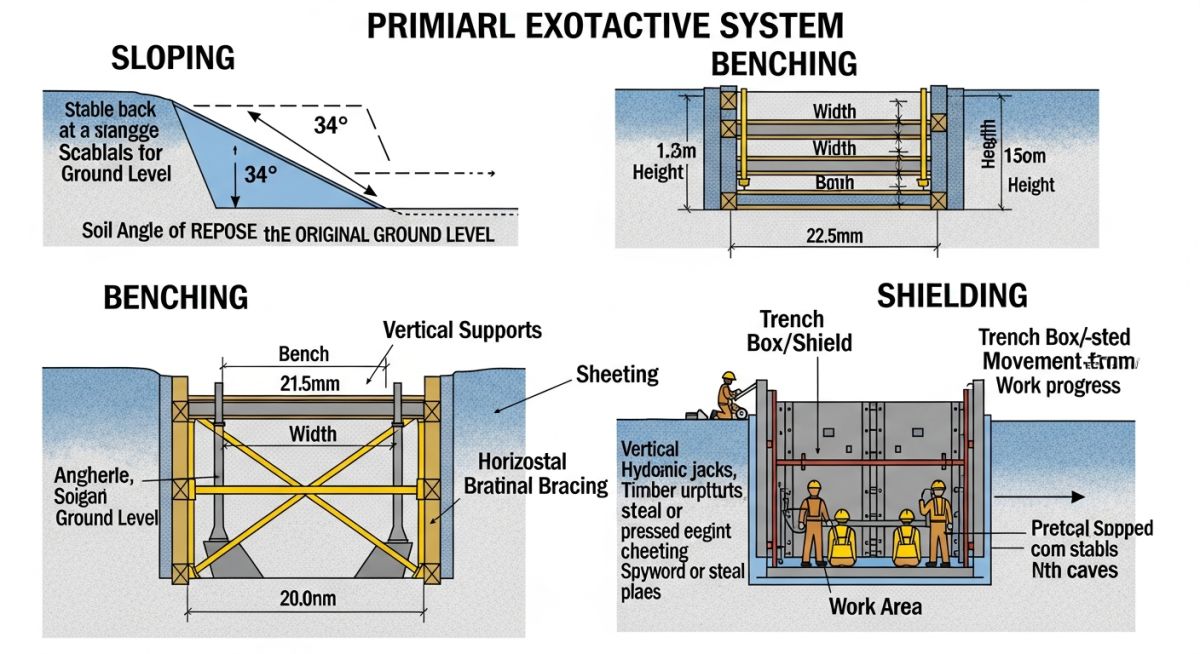
Under OSHA 1926 Subpart P, three primary protective methods are recognized:
- Shoring: A structural system that supports the trench walls, typically using hydraulic aluminum cylinders, timber, or steel sheet piling to prevent soil movement.
- Shielding: The use of trench boxes or shields designed to withstand the forces of a cave-in, protecting workers inside the shield even if the surrounding walls collapse.
- Sloping and Benching: Cutting the trench walls back at an angle safe enough to prevent slide-offs. The angle is determined by the soil classification.
| Soil Type | Unconfined Compressive Strength (tons/sq ft) | Maximum Allowable Slope (H:V) | OSHA Reference |
|---|---|---|---|
| Type A (Cohesive) | 1.5 or greater | 3/4 : 1 (53 degrees) | Appendix A |
| Type B (Cohesive/Granular) | 0.5 to 1.5 | 1 : 1 (45 degrees) | Appendix A |
| Type C (Granular/Saturated) | 0.5 or less | 1.5 : 1 (34 degrees) | Appendix A |
| System Component | Engineering Parameter | Primary Hazard Mitigated | Standard Compliance |
|---|---|---|---|
| Hydraulic Shoring | Cylinder operating pressure (750-1500 psi) | Active wall shear and localized sloughing | Appendix D |
| Trench Shield (Box) | Wall plate thickness and spreader pipe rating | Sudden catastrophic cave-in impact | OSHA 1926.652 |
| Egress Systems | Max 25-foot lateral travel distance | Trapped workers during flooding or collapse | OSHA 1926.651(c) |
Site Verification Checklist
Before allowing any worker to step foot into a trench, the designated competent person must complete a thorough physical inspection. Use this checklist to verify that all safety measures are active and compliant with OSHA 1926.651.
Daily Field Verification Items
-
Utility Locates Verified: All underground utilities (gas, water, electric, fiber) have been marked by the local utility authority and hand-exposed where necessary.
-
Spoil Pile Clearance: Excavated materials and heavy equipment are kept at least 2 feet (0.61 meters) back from the edge of the excavation.
-
Atmospheric Testing: For trenches deeper than 4 feet where hazardous atmospheres could exist, oxygen levels, combustible gases, and toxic contaminants have been tested.
-
Egress Access: Ladders, ramps, or stairs are installed within 25 feet of lateral travel for all workers in trenches 4 feet or deeper.
-
Water Accumulation Control: Pumps or diversion channels are active to prevent water from pooling in the bottom of the excavation.
Implementing Excavation Hazards and Control Measures
The Problem: Unstable Trenching in Saturated Soil
During a municipal sewer upgrade, a contractor was excavating a 14-foot deep trench in Type C sandy soil. Heavy overnight rain saturated the ground, and a 20-ton excavator was operating within 4 feet of the trench edge. The trench walls began to slough, and tension cracks appeared along the surface. The crew was using an unrated, homemade trench box that was not certified for the depth.
The Outcome: Engineered Intervention
As the consulting engineer, I halted work immediately. We removed the unrated box and moved the excavator back to a distance equal to the trench depth (14 feet) to eliminate the surcharge load. We then installed a certified hydraulic aluminum shoring system with heavy-duty plywood sheeting to hold back the saturated sand. Continuous monitoring showed no further movement, and the pipe was laid safely without incident.
This case highlights how quickly a site can deteriorate when dynamic loads (the excavator) and environmental factors (rain) are ignored. Always design your protective systems for the worst-case scenario.
Frequently Asked Engineering Questions
At what depth is an excavation protective system required?
What is the difference between shoring and shielding?
How far back must excavated soil (spoil piles) be kept?
Who qualifies as a “competent person” on an excavation site?
How often must excavations be inspected?
What are the egress requirements for deep trenches?
===FAQ_BLOCK===
📚 Recommended Resources: excavation hazards and control measures
Complete Course on
Piping Engineering
Check Now
Key Features
- 125+ Hours Content
- 500+ Recorded Lectures
- 20+ Years Exp.
- Lifetime Access
Coverage
- Codes & Standards
- Layouts & Design
- Material Eng.
- Stress Analysis
