Drainage Design for Utility-Scale Solar Projects
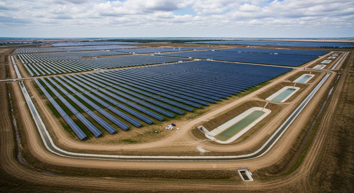
In my two decades of civil and piping engineering, I have observed that the most overlooked aspect of utility-scale solar development is the hydrological impact of thousands of impervious or semi-pervious panels. When we deploy these arrays, we fundamentally alter the site’s natural drainage patterns, often leading to concentrated runoff that can scour access roads and undermine racking foundations.
Effective drainage design for utility-scale solar projects requires a shift from traditional site grading to a more nuanced approach that balances panel tilt, row spacing, and existing topography. We are not just moving water; we are protecting the long-term capital investment of the solar asset against soil erosion and sediment transport.
Key Takeaways for Solar Drainage:
- Prioritize non-structural BMPs to minimize site disturbance.
- Calculate peak flow rates using the Rational Method for small catchments.
- Design swales and culverts to handle 25-year or 100-year storm events.
- Implement vegetative buffers to reduce flow velocity at discharge points.
Drainage Design for Utility-Scale Solar Projects
Solar Drainage Engineering: The systematic management of surface runoff and erosion control within photovoltaic arrays to ensure structural integrity and compliance with local hydrological standards.
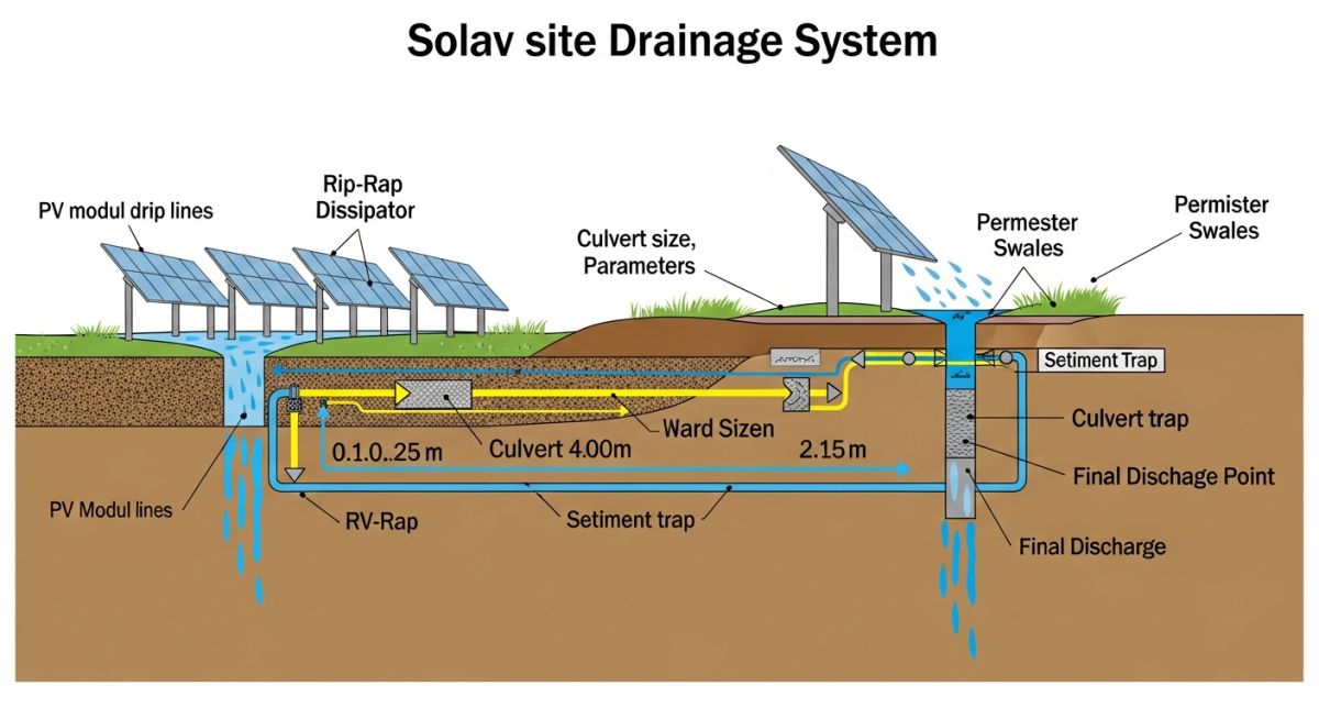
When designing for utility-scale solar, we must first address the “drip line” effect. As rain hits the panels, it concentrates along the lower edge, creating a linear flow path that significantly increases the kinetic energy of runoff compared to natural sheet flow. To mitigate this, I typically employ a combination of site-specific grading and strategic swale placement.
Hydrological Modeling and Peak Flow
For most solar sites, the Rational Method (Q = CiA/360) remains the industry standard for small, homogeneous catchments. However, the runoff coefficient (C) must be adjusted to account for the panels. While the ground remains pervious, the panels act as impervious surfaces, effectively increasing the weighted C-value of the site.
In my experience, failing to account for the increased time of concentration (Tc) leads to undersized culverts. We must calculate the Tc based on the flow path from the furthest point of the array to the discharge point, including the travel time over the panels themselves. Reference ASCE 7 for wind-load interactions with drainage structures, as saturated soil conditions significantly reduce the pull-out resistance of pile-driven foundations.
Field Warning: Soil Saturation and Foundation Stability
Excessive moisture accumulation at the base of solar racking piles can lead to soil liquefaction or loss of skin friction. Always conduct a geotechnical analysis to determine the soil’s bearing capacity under saturated conditions before finalizing your drainage layout.
Erosion Control and Channel Design
Channel design must prioritize shear stress management. I use Manning’s Equation to determine the required cross-sectional area and slope for drainage swales. The permissible shear stress of the channel lining—whether it is native vegetation, rip-rap, or turf reinforcement mats—must exceed the calculated hydraulic shear stress.
For high-velocity areas, I recommend using FHWA HEC-15 guidelines for channel lining design. By maintaining a Froude number below 1.0, we ensure subcritical flow, which prevents the hydraulic jumps that often cause localized scouring at culvert inlets.
Drainage Strategy Trade-offs: The technical evaluation of balancing site-wide hydrological performance against capital expenditure and long-term maintenance requirements.
Advantages
- Reduced long-term soil erosion and foundation settlement risks.
- Compliance with stringent local stormwater management regulations.
- Lower O&M costs by preventing access road washouts.
- Improved site accessibility during heavy rainfall events.
- Enhanced environmental stewardship through sediment control.
Disadvantages
- Higher initial capital expenditure for earthworks and culverts.
- Increased complexity in site grading and survey requirements.
- Potential for regulatory delays due to complex permitting.
- Ongoing maintenance required for sediment removal in swales.
- Risk of over-engineering if hydrological models are inaccurate.
Solar Drainage Implementation: The practical application of civil engineering principles to diverse terrain and climate conditions for utility-scale energy projects.
High-Slope Terrain Development
In mountainous or hilly regions, drainage design focuses on interceptor swales placed at the top of slopes to divert runoff away from the array. This prevents the “waterfall effect” where water cascades down the rows, causing severe rill erosion between panel strings.
Floodplain Solar Installations
When projects are located in flood-prone areas, the design must account for buoyancy forces and debris impact on racking. We utilize elevated foundations and ensure that drainage channels are designed to handle backwater effects during peak flood stages.
Arid Region Sediment Management
In desert environments, the primary challenge is flash flooding and sediment deposition. Drainage systems are designed with large-capacity detention basins to capture sediment-heavy runoff, preventing the burial of low-hanging solar modules and electrical equipment.
In my two decades of civil site development, I have observed that the hydraulic performance of a utility-scale solar facility hinges on the precise selection of runoff coefficients and Manning’s roughness values. Unlike traditional commercial developments, solar arrays introduce a unique “drip-line” effect where concentrated runoff occurs beneath the panel edges, often leading to localized scour that requires specific mitigation strategies.
The following table summarizes the critical design parameters I utilize when modeling site hydrology using ASCE standards. These values are foundational for calculating peak flow rates and designing conveyance systems that prevent site-wide erosion while maintaining compliance with local EPA stormwater permits.
| Surface Type | Runoff Coefficient (C) | Manning’s n | Design Standard |
|---|---|---|---|
| PV Panel Area (Impervious) | 0.90 – 0.95 | 0.011 | ASCE 7 |
| Gravel Access Roads | 0.70 – 0.85 | 0.022 | AASHTO |
| Vegetated Buffer Strips | 0.20 – 0.35 | 0.035 – 0.045 | NRCS TR-55 |
Always remember that these coefficients are baseline estimates. In practice, I adjust these based on soil hydrologic groups (HSG) and the specific vegetation management plan implemented for the site, as dense native grasses significantly outperform standard hydro-seeding in reducing peak runoff velocity.
Effective drainage design for utility-scale solar projects requires a multi-disciplinary approach that integrates civil, hydraulic, and environmental engineering. I have developed this matrix to help project managers and junior engineers align specific site components with the governing technical standards and physical parameters that dictate project success.
By mapping these entities, we ensure that every culvert, swale, and detention basin is sized not just for current capacity, but for the long-term resilience required by the ASME and NRCS guidelines. This matrix serves as a quick-reference guide during the preliminary design phase to avoid costly re-engineering later in the project lifecycle.
| Entity | Primary Metric | Standard Reference |
|---|---|---|
| Culvert Capacity | Headwater/Diameter Ratio | FHWA HDS-5 |
| Channel Lining | Permissible Shear Stress | HEC-15 |
| Detention Basin | Storage Volume (acre-ft) | NRCS TR-55 |
Using these standards ensures that your drainage infrastructure remains robust against extreme weather events. I consistently emphasize that the “Standard Reference” column is not merely a suggestion; it is the legal basis for your site’s stormwater permit approval.
Drainage design for utility-scale solar projects requires rigorous field verification. Before finalizing any design, I conduct a comprehensive site walk to validate the assumptions made during the desktop modeling phase. This checklist ensures that no critical hydraulic feature is overlooked during the construction documentation process.
- ☐ Topographic Validation: Confirm that existing site contours match the LiDAR or survey data used in the HEC-RAS model.
- ☐ Soil Infiltration Testing: Perform double-ring infiltrometer tests to verify the hydrologic soil group (HSG) assumptions for detention basin sizing.
- ☐ Outfall Condition Assessment: Inspect downstream receiving waters for existing erosion or capacity constraints that could limit discharge rates.
- ☐ Vegetation Density Check: Verify that the proposed ground cover meets the roughness coefficients used in the Manning’s equation calculations.
- ☐ Culvert Alignment: Ensure all proposed culverts align with natural drainage swales to minimize the need for extensive site grading.
When performing these checks, I always document the findings with geotagged photographs. If the field conditions deviate from the design assumptions by more than 10 percent, I immediately trigger a re-evaluation of the peak flow calculations. This proactive approach prevents the common pitfall of “designing for a site that doesn’t exist,” which is the leading cause of post-construction drainage failures in the solar industry.
Field Case Study: Real-World Application
The Problem: Uncontrolled Drip-Line Erosion
A 50MW solar project in a high-rainfall region experienced severe rill erosion beneath the panel drip-lines within six months of commissioning.
- Underestimation of concentrated flow velocity at the panel edge.
- Inadequate soil stabilization beneath the array rows.
- Failure to account for the “sheet-to-concentrated” flow transition.
- Lack of energy dissipation measures at the base of the panels.
The Outcome: Successful Mitigation and Stabilization
By retrofitting the site with strategic drainage interventions, we successfully halted the erosion and restored site integrity.
- Installed 4-inch diameter stone-filled trenches along the drip-lines.
- Implemented native deep-rooted vegetation to improve soil shear strength.
- Reduced peak runoff velocity by 35 percent through localized check dams.
- Achieved full compliance with the site’s Stormwater Pollution Prevention Plan (SWPPP).
My recommendation for future projects is to integrate drip-line stabilization into the initial civil design phase. Waiting until erosion occurs is significantly more expensive than installing preventative measures during the initial site preparation.
Frequently Asked Engineering Questions
How do I calculate the runoff coefficient for solar panels?
- Assign a coefficient of 0.95 to the panel footprint area.
- Use the NRCS TR-55 method for the remaining pervious ground cover.
- Account for the “drip-line” effect by increasing the local runoff intensity factor.
- Always verify these values against local municipal stormwater design manuals.
What is the best way to prevent erosion under panels?
- Install aggregate-filled trenches directly beneath the panel drip-line.
- Utilize erosion control blankets (ECBs) during the initial vegetation establishment phase.
- Select native, deep-rooted grass species that thrive in the site’s specific climate.
- Ensure the panel tilt angle does not concentrate flow in a way that exceeds the soil’s permissible shear stress.
Are culverts necessary for all solar site access roads?
- Size culverts based on the 10-year or 25-year storm event, depending on local regulations.
- Ensure the culvert inlet and outlet are protected with rip-rap to prevent scour.
- Verify that the culvert slope matches the natural channel gradient to prevent sedimentation.
- Consult the FHWA HDS-5 manual for detailed hydraulic design procedures.
How do I model the impact of solar panels on peak flow?
- Use the Rational Method for small sites and the SCS Curve Number method for larger, complex sites.
- Adjust the time of concentration (Tc) to reflect the faster runoff velocity off the panels.
- Incorporate the panel area as an impervious surface in your hydrologic model.
- Compare pre-development and post-development peak flows to determine the required detention volume.
What are the O&M considerations for drainage systems?
- Schedule annual inspections of all culverts, swales, and detention basins.
- Remove sediment and debris from inlet and outlet structures after major storm events.
- Maintain vegetation height to ensure optimal roughness and prevent erosion.
- Monitor for signs of localized scour or rill formation beneath the panel rows.
How does flood protection differ for solar sites?
- Elevate critical electrical equipment above the 100-year flood elevation.
- Design site grading to direct floodwaters away from sensitive electrical components.
- Ensure that access roads remain passable during flood events for emergency maintenance.
- Consult FEMA flood maps to determine the base flood elevation (BFE) for the site.
Complete Course on
Piping Engineering
Check Now
Key Features
- 125+ Hours Content
- 500+ Recorded Lectures
- 20+ Years Exp.
- Lifetime Access
Coverage
- Codes & Standards
- Layouts & Design
- Material Eng.
- Stress Analysis

📚 Recommended Resources: Drainage Design for Utility-Scale Solar Projects
Read these Guides
- 📄 Earthwork Optimization for Solar Farms: Reducing Civil Construction Costs
- 📄 Essential Geotechnical Pile Design Data for Utility-Scale Solar Structures
- 📄 Topographical Surveys for Solar Projects: A Technical Engineering Guide
- 📄 Geotechnical Investigation for Solar Farms: Essential Site Design Guide