Determination of Design Pressure and Design Temperature: Engineering Standards 2026
Imagine a high-pressure separator failing in a hydrocracking unit simply because a transient surge was ignored during the FEED stage. For many piping and mechanical engineers, the Determination of Design Pressure and Design Temperature is more than a calculation—it is the fine line between structural integrity and catastrophic rupture. Selecting values too low risks safety, while values too high lead to “gold-plating” that can inflate project costs by millions.
In this guide, we bridge the gap between process simulation data and mechanical fabrication standards, ensuring your equipment meets ASME Section VIII requirements while remaining economically viable.
Key Learning Outcomes
- Establish the mandatory margins between operating and design envelopes.
- Identify the critical impact of MDMT and steam-out conditions on material selection.
- Differentiate between Design Pressure and MAWP for compliance with international codes.
What is Design Pressure and Temperature?
The Determination of Design Pressure and Design Temperature involves setting maximum limits above normal operating conditions to account for process upsets. Typically, design pressure is the highest coincident pressure plus a 10% or 25 psi margin, while design temperature is the maximum operating temperature plus 25°F to 50°F safety margin.
“Over 20 years in EPC projects, I’ve seen the most confusion in heat exchanger design. It is crucial to remember that the determination of design pressure must consider the highest pressure of either the shell or tube side to account for internal tube leaks.”
— Atul Singla, Founder of EPCLand
Table of Contents
Complete Course on
Piping Engineering
Check Now
Key Features
- 125+ Hours Content
- 500+ Recorded Lectures
- 20+ Years Exp.
- Lifetime Access
Coverage
- Codes & Standards
- Layouts & Design
- Material Eng.
- Stress Analysis
Engineering Challenge: Design Parameters Quiz
Test your knowledge on Pressure and Temperature determination.
1. What is the typical minimum margin added to the maximum operating pressure to determine Design Pressure?
The Role of Operational Data in Determination of Design Pressure and Design Temperature
The Determination of Design Pressure and Design Temperature begins with a rigorous analysis of the process simulation. Operational data provides the baseline, but the “Normal Operating Point” is rarely the design point. Engineers must scrutinize Heat and Material Balances (HMB) to identify the “worst-case” scenario. This includes startup, shutdown, regeneration cycles, and emergency depressurization. For instance, a vessel might operate normally at 150°C, but during a catalyst regeneration phase, it could reach 220°C. In such cases, the higher value—plus a safety margin—must dictate the design parameters to ensure the mechanical integrity of the pressure boundary.
Construction Data Requirements for Pressure Equipment
Once the process parameters are established, construction data translates these needs into physical reality. This phase involves selecting materials that can withstand the calculated design envelope without losing structural ductility. According to the ASME Section VIII, the mechanical properties of materials vary significantly with temperature. Therefore, the determination of design temperature directly influences the allowable stress values used in wall thickness calculations. Construction data also accounts for corrosion allowances, joint efficiency, and nozzle loadings, ensuring that the physical asset can endure the design pressure over its intended 20-to-30-year lifecycle.
Integrating Client Design Philosophy and ITB Requirements
Every major operator—from Shell to ExxonMobil—has a unique “Design Philosophy” embedded in their Invitation to Bid (ITB) documents. These internal standards often supersede general codes like ASME. For example, a client philosophy may mandate a minimum design pressure of 3.5 barg (50 psig) for any vessel, even if the process operates at atmospheric pressure, to prevent accidental overpressure during steam cleaning or nitrogen purging. Adherence to these site-specific rules is a non-negotiable step in the Determination of Design Pressure and Design Temperature.
Expected Output Data and Deliverables
The final output of this determination process is the Mechanical Data Sheet. This document serves as the master reference for the fabrication shop. It must clearly state the Design Pressure, Maximum Allowable Working Pressure (MAWP), Design Temperature (Internal/External), and the Minimum Design Metal Temperature (MDMT). These values are used by the manufacturer to perform the final stress analysis and to select the appropriate Welding Procedure Specifications (WPS). You can find more detailed guidance on equipment documentation at the Official ASME Website.
Criteria for Determination of Design Pressure in Pressure Vessels
For a single-phase pressure vessel, the Determination of Design Pressure usually follows a “10% or 25 psi” rule—whichever is greater. If the maximum operating pressure is 100 psi, the design pressure becomes 125 psi. However, for tall towers or liquid-filled vessels, static head must be added to the pressure at the bottom. This ensures that the lowest point of the vessel, which experiences the weight of the fluid column plus the vapor pressure, remains within safe limits. Failure to account for static head is a common error in large-scale refinery column design.
Step-by-Step Calculation: Example 1
Consider a vertical separator with a Maximum Operating Pressure (MOP) of 45 barg at the top nozzle. The liquid height is 10 meters with a density of 800 kg/m3.
- Step 1: Apply 10% Margin: 45 barg * 1.10 = 49.5 barg.
- Step 2: Calculate Static Head: (10m * 800 kg/m3 * 9.81) / 100,000 = 0.78 bar.
- Step 3: Determine Design Pressure at Bottom: 49.5 + 0.78 = 50.28 barg.
- Conclusion: The vessel design pressure is specified as 50.3 barg at the top to satisfy all conditions.
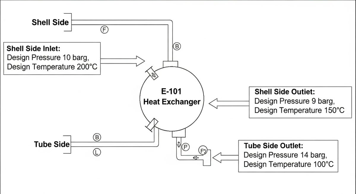
Determination of Design Pressure for Heat Exchangers
The Determination of Design Pressure for heat exchangers is significantly more complex than for static vessels due to the interaction between two independent fluid circuits. According to API Standard 660 and TEMA standards, the shell-side and tube-side must be designed for their respective maximum operating pressures plus a safety margin. However, a critical safety consideration is the “Tube Rupture” scenario. If the high-pressure side operates at a pressure more than 1.3 times the low-pressure side’s design pressure, the low-pressure side must be protected by a relief device or be designed to withstand the higher pressure. This “10/13th Rule” (based on ASME Section VIII Div 1 hydrotest margins) ensures that a single tube failure does not lead to a catastrophic shell-side rupture.
Establishing Equipment Design Pressure Margins
When finalizing the Determination of Design Pressure, engineers must account for the gap between the Pressure Safety Valve (PSV) set point and the operating pressure. A common mistake is setting the design pressure too close to the operating pressure, leading to “simmering” or premature lifting of the relief valve due to minor process fluctuations. API RP 520 recommends a minimum 10% margin to allow the PSV to seat properly. In high-pressure services (above 70 bar), this margin might be narrowed to 5% to reduce wall thickness and cost, provided high-accuracy pilot-operated relief valves are utilized.
Best Practices for Determination of Design Temperature
The Determination of Design Temperature is not merely selecting the highest operating temperature. It must account for “Excursion Conditions” such as loss of cooling water, catalyst runaway, or solar radiation on stagnant lines. For equipment operating above 400°C (750°F), creep-strength-enhanced ferritic steels or austenitic stainless steels are required. Conversely, for cryogenic services, the design temperature must reflect the lowest possible fluid temperature to avoid brittle fracture. Detailed material temperature limits can be verified through the API Standards Portal.
Calculating Minimum Design Metal Temperature (MDMT)
The Minimum Design Metal Temperature (MDMT) is the lowest temperature at which a component can safely withstand its design pressure. Determination of MDMT is critical for carbon steel vessels in cold climates or those containing liquefied gases. If a vessel undergoes rapid depressurization (blowdown), the Joule-Thomson effect can drop the metal temperature to -40°C or lower. If the MDMT is not correctly specified, the steel becomes brittle and can fail via “cleavage fracture” even at pressures below the design limit. ASME Section VIII Div 1 Paragraph UCS-66 provides the governing impact test exemption curves used to establish these limits.
Impact of Steam-out Conditions on Design Temperature
During maintenance turnarounds, vessels are often “steamed out” to remove hydrocarbons. This process usually involves low-pressure steam at approximately 120°C to 150°C. If the normal operating temperature of a vessel is lower (e.g., 60°C), the Determination of Design Temperature must be bumped up to the steam-out temperature. Additionally, engineers must check for “Full Vacuum” conditions. When steam condenses inside a blocked-in vessel, it creates a vacuum that can collapse the shell if it was not designed for external pressure.
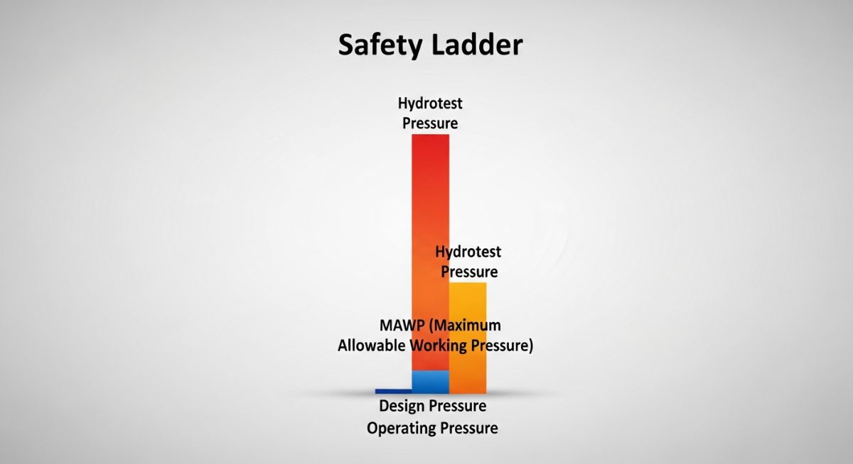
Comparison: Design Pressure vs. Maximum Allowable Working Pressure (MAWP)
While often used interchangeably, these terms have distinct legal meanings under ASME Code. The Design Pressure is the value specified by the process engineer. The MAWP is the maximum pressure at which the weakest part of the finished vessel can operate at a specific temperature. MAWP is always equal to or greater than the Design Pressure because it is based on the actual “as-built” thickness (including extra thickness from rounding up plate sizes).
| Parameter | Basis of Determination | Typical Margin | Governing Code |
|---|---|---|---|
| Design Pressure | Max Operating Pressure (MOP) | 10% or 25 psi (1.7 bar) | ASME VIII Div 1 |
| Design Temperature | Max Operating Temp (MOT) | 25°F to 50°F (15°C to 28°C) | ASME II Part D |
| MDMT | Auto-refrigeration / Ambient | Lowest Coincident Temp | ASME VIII UCS-66 |
| External Pressure | Vacuum / Steam-out | Full Vacuum (1.03 bar) | ASME VIII UG-28 |
Design Margin Calculator (2026 Edition)
Quickly calculate the Determination of Design Pressure and Design Temperature margins based on standard engineering protocols.
Recommended Values
Note: Pressures use a 10% margin or 25 psi (1.7 bar) rule. Temperatures use a 50°F (28°C) margin per standard Determination of Design Pressure and Design Temperature practices.
Case Study: Solving Design Pressure Discrepancies in Shell & Tube Exchangers
The Challenge
A refinery expansion project required the Determination of Design Pressure and Design Temperature for a new Crude Pre-heat Exchanger where the tube-side crude (45 barg) significantly exceeded the shell-side desalter water (5 barg).
The Risk
A tube rupture would instantly overpressurize the shell-side, leading to a loss of primary containment. The existing shell-side relief valve was sized only for thermal expansion, not a full tube break.
The Solution
Applied the “10/13th Rule” from API 521. The shell-side design pressure was increased to 35 barg (10/13th of 45 barg) to eliminate the need for a massive, costly atmospheric relief system.
Implementation Results
By adjusting the Determination of Design Pressure during the FEED phase, the engineering team avoided the installation of a 12-inch flare header extension. Instead, the shell thickness was increased by only 4mm, representing a net project saving of $140,000 in piping and structural supports.
This case highlights why the Determination of Design Pressure and Design Temperature must look beyond “normal operation” and account for credible failure scenarios defined in ASME Section VIII and API 521.
EPCLand YouTube Channel
2,500+ Videos • Daily Updates
Expert Insights: Lessons from 20 years in the field
- 1 The “Locked-in” Trap: Always verify if your Determination of Design Pressure accounts for the maximum shut-off head of centrifugal pumps. Designing only for the normal discharge pressure leads to repeated PSV lifting during startup.
- 2 Material Limits: Carbon steel (A106-B/A516-70) undergoes a significant drop in allowable stress above 343°C (650°F). In the Determination of Design Temperature, if your process hits 350°C, consider switching to low-alloy steels like 1.25Cr-0.5Mo to maintain structural integrity without excessive wall thickness.
- 3 Vacuum Hazards: Never assume a vessel is “atmospheric.” During the Determination of Design Pressure, always evaluate the risk of internal condensation or liquid pump-out without adequate venting, which necessitates a Full Vacuum (FV) rating.
- 4 The 10/13th Rule Nuance: In modern projects, while the 10/13th rule (77% of high-side pressure) is a common threshold for shell-and-tube exchangers, many European operators now insist on a 100% design pressure match to avoid the complexity of tube-rupture relief systems entirely.
References & Standards
Global Engineering Compliance Documents:
- ASME Section VIII Div. 1: Rules for Construction of Pressure Vessels
- API Standard 521: Pressure-Relieving and Depressurizing Systems
- API Standard 520: Sizing and Selection of Pressure-Relief Devices
- API Standard 660: Shell-and-Tube Heat Exchangers
- ISO 23251: Petroleum, Petrochemical, and Natural Gas Industries
- ASME Section II Part D: Material Properties
Frequently Asked Questions: Determination of Design Pressure and Design Temperature
What is the standard margin for Determination of Design Pressure? ▼
How is Design Temperature determined in high-heat processes? ▼
What is the difference between Design Pressure and MAWP? ▼
Why does steam-out affect the Determination of Design Temperature? ▼
How do pump shut-off heads impact the Determination of Design Pressure? ▼
Is impact testing required for all vessels at MDMT? ▼
📚 Recommended Resources: Determination of Design Pressure and Design Temperature
Read these Guides
- 📄 Slurry Piping System Design: Engineering Guide & Standards 2026
- 📄 Remaining Life of Pressure Vessels Based on Corrosion Rate
- 📄 Pipe Thickness Calculations for Process, Hydrogen, and Power Plant Piping: Understanding ASME Codes and Calculation Parameters
- 📄 Characteristics of Crude Oil: Engineering Guide & Data 2026


Related posts:
![High-grade industrial Wing Nut Types and Applications for mechanical assemblies.]()
Wing Nut Types and Applications: The 2026 Engineering Guide
![Industrial Monorail Crane Systems installed in a modern manufacturing plant 2026.]()
Monorail Crane Systems: Design, Types & 2026 Standards Guide
![Lead engineer performing a Factory Acceptance Test FAT on an industrial skid system 2026]()
Factory Acceptance Test FAT: The 2026 Engineering Guide to Zero-Defect Delivery
![Professional engineering workspace showing a Basis of Design document layout for a 2026 project.]()
Basis of Design: How to Write a BOD for Engineering Projects in 2026
![Industrial Flare Knockout Drum Sizing and installation in a refinery relief system.]()
Flare Knockout Drum Sizing: Design & API 521 Standards (2026 Guide)
![Advanced Reboiler Control Systems in a modern petrochemical refinery 2026.]()
Reboiler Control Systems: Engineering Guide to Precision Control 2026


