Preventing Cavitation in Control Valves Using Multi-Stage Cage-Guided Trim
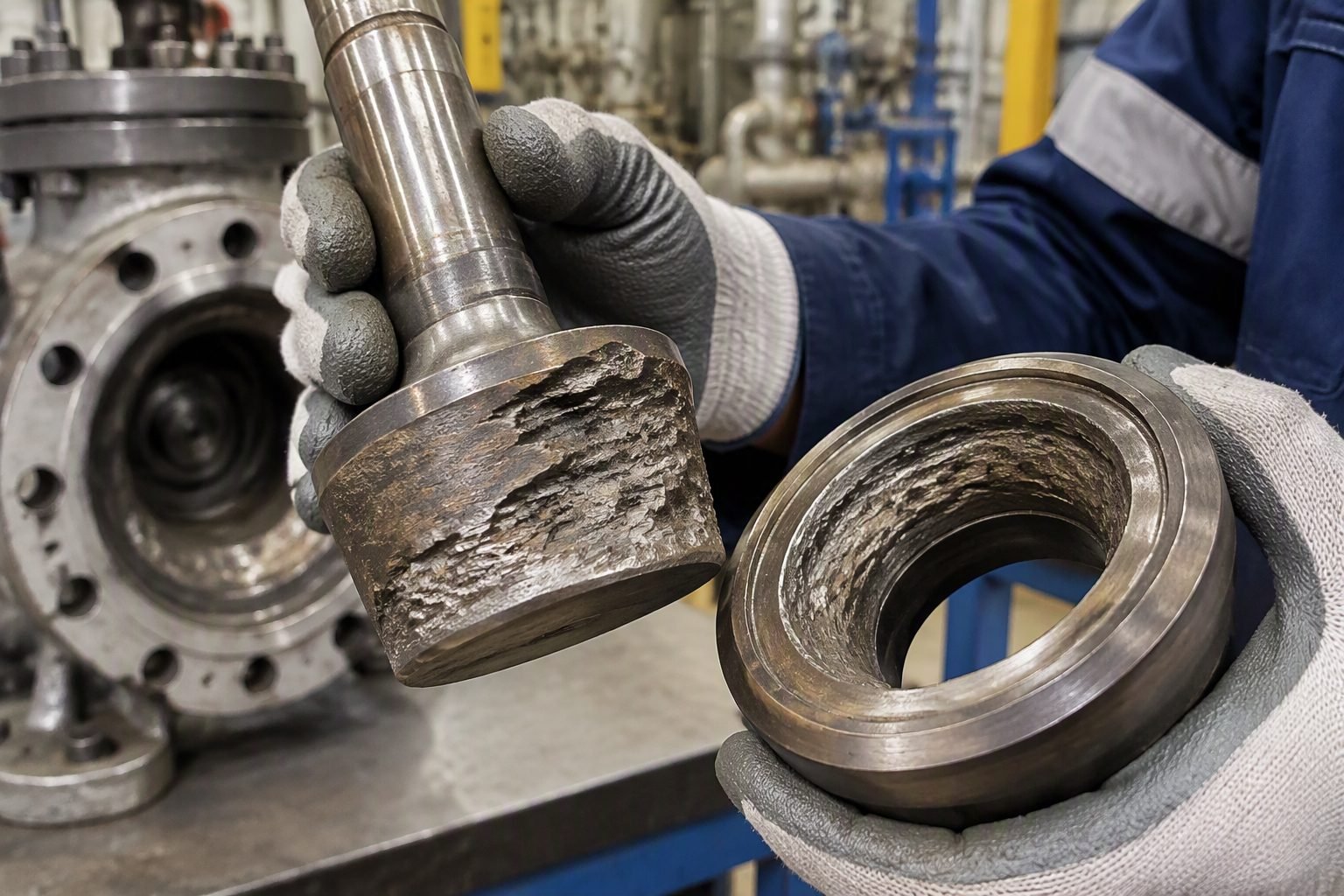
In my two decades of reviewing high-pressure liquid letdown loops across refining and petrochemical units, I have witnessed firsthand how uncontrolled cavitation can reduce a hardened stainless steel valve body to honeycomb scrap within weeks. When high-velocity fluids flash or cavitate across traditional single-seat plugs, the resulting shockwaves strip away boundary material and trigger violent pipe vibrations.
To solve this persistent reliability challenge, modern process facilities rely on sophisticated cage-guided control valve architectures. By replacing conventional plugs with concentrically stacked, perforated metal discs, these engineered trims divide the total pressure drop into manageable increments.
Key Engineering Takeaways
- Staging pressure drops prevents the local fluid pressure from dipping below the vapor pressure limit.
- Concentric perforated discs balance radial forces, providing superior plug stability under turbulent flow.
- Adherence to ISA-75.01.01 sizing standards ensures accurate prediction of valve pressure recovery factors.
- Proper material selection, such as Stellite hardfacing or tungsten carbide, resists minor particle impingement.
Cavitation Mechanics and Cage-Guided Trim Fluid Dynamics
Understanding the fundamental mechanics of liquid vaporization requires evaluating the vena contracta. When a process fluid passes through a restriction like a traditional valve seat, its velocity increases dramatically while its static pressure drops to the lowest point at the vena contracta.
If this localized static pressure falls below the liquid vapor pressure at the flowing temperature, vapor bubbles form instantly. As the fluid recovers downstream and pressure rises above the vapor pressure, these bubbles collapse violently with micro-jet velocities exceeding 1,000 meters per second.
The Physics of Multi-Stage Pressure Drop Staging
Multi-stage cage-guided trim disrupts this destructive cycle by substituting a single massive pressure drop with four to six sequential, smaller drops. Each concentric disc features meticulously sized micro-perforations or tortuous fluid paths.
As the high-pressure liquid enters the inner cylinder, it forces its way through the first tier of holes. This initial drop is calculated so that the resulting intermediate pressure remains safely above the fluid vapor pressure threshold.
The fluid then expands into the intermediate annular space between the first and second cages before entering the next set of restrictions. By stepping the pressure down incrementally across these successive stages, the kinetic energy is dissipated evenly throughout the entire cage volume rather than focusing on the solid downstream piping walls.
Critical Design Warning: Upstream Particulates
Multi-stage cages feature extremely tight flow clearances and micro-drilled orifices. Implementing these trims without upstream filtration or strainers in dirty services will cause rapid plugging, severe flow capacity reduction, and potential mechanical binding of the valve plug.
Mathematical Sizing and Cavitation Index Verification
Sizing valves with anti-cavitation trim requires strict adherence to ISA-75.01.01 standards. Engineers calculate the cavitation index parameter (Sigma) to determine whether vapor formation will occur under maximum operating differentials.
The Sigma index is expressed as the ratio of upstream pressure minus vapor pressure divided by upstream pressure minus downstream pressure. When Sigma drops below the characteristic valve cavitation inception limit (Sigma i), damage begins.
By integrating a multi-stage cage, the effective valve pressure recovery factor increases significantly. This pushes the operating Sigma well above the threshold of damage, ensuring smooth, reliable modulation through high-pressure letdown loops.
Mechanical Stability and Cage-Guided Alignment
Beyond fluid dynamics, cage-guided trims provide exceptional mechanical support to the valve plug. Traditional top-guided valves suffer from side-load deflection and stem fatigue when subjected to high-velocity turbulent jetting across asymmetrical openings.
A heavy-wall cylindrical cage completely surrounds the plug, offering a large guiding surface area along the entire stroke length. This robust mechanical containment eliminates plug chatter, suppresses high-frequency acoustic noise, and maintains precise alignment even during high-pressure liquid flashes.
Engineering Advantages
- Complete Cavitation Elimination: Staging pressure drops keeps local fluid pressure above vapor pressure limits, halting bubble collapse.
- Superior Mechanical Stability: Heavy cylindrical walls provide full-stroke plug guidance, preventing side-load vibration and stem fatigue.
- Acoustic Noise Reduction: Energy dissipation across micro-perforations lowers operating noise levels by up to 15 decibels.
- Extended Service Life: Hardened metal alloys and distributed wear patterns protect internal body components from premature erosion.
- High Turndown Capability: Precise flow characterization over wide operating ranges improves overall loop stability.
Engineering Disadvantages
- High Capital Expenditure: Multi-stage stacked discs require precision machining, significantly increasing upfront procurement costs.
- Particulate Intolerance: Small flow orifices make the trim vulnerable to plugging from suspended solids or weld slag in the line.
- Increased Weight and Size: Valve assemblies are bulkier and heavier, requiring additional pipe supports during installation.
- Complex Maintenance: Disassembling multi-component stacked disc cages requires specialized technician training and tooling.
- Lower Flow Capacity: Restrictive internal flow paths reduce maximum valve flow coefficient (Cv) compared to unthrottled designs.
High-Pressure Boiler Feedwater Systems
Boiler feedwater pump recirculation and drum level control valves experience massive pressure drops exceeding 150 bar. Multi-stage cage-guided trims break down this immense energy differential, preventing aggressive metal loss on trim components and ensuring reliable steam generation.
Refinery Hydroprocessing Letdown Loops
Hydrocracker and hydrotreater high-pressure separator liquid letdown valves handle multi-phase hydrocarbon mixtures at elevated temperatures. Implementing concentric stacked disc cages prevents destructive cavitation and flashing during severe fluid depressurization.
LNG Liquefaction and Cryogenic Letdown
Liquefied natural gas processing plants require precise pressure reduction of cryogenic fluids where flashing can destroy standard trim. Staged perforated discs manage the phase change smoothly, maintaining stable process control and preventing thermal shock.
High-Capacity Seawater Desalination Plants
Reverse osmosis energy recovery and reject brine disposal systems operate under immense hydrostatic pressures. Cage-guided control valves constructed with super duplex stainless steel resist both cavitation erosion and aggressive saltwater corrosion.
Chemical Synthesis High-Pressure Letdown
High-pressure reactor effluent and ammonia plant letdown loops involve severe operating conditions and corrosive process media. Multi-stage pressure drop staging protects internal trim surfaces from localized pitting and violent cavitation damage.
Cage-Guided Control Valve Trim Performance and Material Specifications
Designing multi-stage pressure reduction components requires meticulous alignment between fluid thermo-physical properties and mechanical metallurgy. In my experience across high-pressure hydrocarbon letdown stations, selecting improper trim metallurgy or incorrect flow characterization curves leads to rapid wire-drawing and catastrophic acoustic fatigue within months of commissioning. The engineering data table below outlines the critical structural parameters, ASME material classifications, and operational thresholds governing multi-stage cage-guided control valve trim assemblies.
Compliance with ASME B16.34 and ISA 75.01.01 ensures that the physical staging of pressure drops across concentric perforated discs maintains the vena contracta pressure above the fluid vapor pressure. This specific design philosophy prevents vapor bubble collapse, protecting the valve body and downstream piping from severe localized pitting. Review these parameters carefully when sizing high-pressure liquid service loops.
| Trim Parameter / Specification | Standard Operational Limit | Applicable Engineering Code |
|---|---|---|
| Maximum Pressure Drop Ratio (Delta P / P1) | Up to 0.85 per stage without flashing | ISA-75.01.01 |
| Standard Cage Material | ASTM A476 / UNS S31603 with Stellite Hardfacing | ASME B16.34 |
| Perforation Flow Velocity Limit | Maximum 15 m/s across vena contracta | API 553 |
| Acoustic Noise Threshold | Maximum 85 dBA at 1 meter distance | IEC 60534-8-3 |
| Leakage Class Rating | Class V or VI shutoff capability | FCI 70-2 |
Proper integration of these material grades and velocity constraints guarantees prolonged mechanical integrity in aggressive multi-phase processing environments.
Technical Mapping & Specifications Matrix
To streamline the procurement and engineering review workflow, mapping physical system components against standardized nomenclature is essential. This entity data matrix outlines the core structural acronyms, physical parameters, and corresponding regulatory guidelines that govern cage-guided control valve trim designs. In my plant troubleshooting assignments, utilizing a standardized matrix ensures multidisciplinary teams interpret pressure staging data identically.
Each entry cross-references specific industrial standards maintained by organizations such as ASME and ISO. Reviewing this matrix clarifies the functional relationships between cavitation index parameters, plug guiding tolerances, and velocity management strategies implemented in modern severe-service control valves.
| System Entity / Acronym | Physical Description & Function | Governing Standard Reference |
|---|---|---|
| FL (Liquid Pressure Recovery Factor) | Quantifies pressure loss between valve inlet and vena contracta | ISA-75.01.01 |
| Kc (Cavitation Index) | Defines threshold where incipient cavitation begins in liquid flow | IEC 60534-2-1 |
| Multi-Stage Cage (MSC) | Concentric perforated discs engineered for staggered pressure drops | ASME B16.34 |
| Balanced Plug (BP) | Utilizes internal balancing seals to reduce actuator thrust requirements | ISO 5208 |
| Stellite Overlay (ST) | Cobalt-base alloy weld overlay providing extreme erosion resistance | AWS D1.1 |
By adhering to these standardized entity definitions, engineers can specify, inspect, and maintain complex valve trims with absolute confidence across international project sites.
Site Verification Checklist for Cage-Guided Control Valve Trim
Inspecting a newly overhauled or commissioned multi-stage cage-guided control valve trim requires strict adherence to pre-startup safety and mechanical verification protocols. Drawing from my commissioning experience on high-pressure boiler feedwater systems, overlooking minor alignment tolerances or debris inside the perforated discs invariably results in premature trim binding and severe flow regulation failure.
This comprehensive checklist outlines the exact verification checkpoints required to ensure compliance with ASME B16.34 and ISA quality standards before introducing process fluids into the piping network.
Pre-Commissioning Inspection & Validation Checkpoints
Completing every item on this verification checklist guarantees that the pressure staging trim will operate smoothly, eliminating unexpected vibration and cavitation damage during initial plant startup.
Field Case Study: Multi-Stage Cavitation Mitigation in High-Pressure Letdown
During the commissioning of a high-pressure boiler feedwater letdown station in a 1,200 MW supercritical power facility, severe mechanical vibration and deafening acoustic noise developed across the primary pressure control valve whenever throughput exceeded 65 percent capacity. The original single-stage control valve trim experienced severe cavitation pitting, eroding the plug and seat ring within 500 hours of operation.
Field Problem Analysis
Single-stage pressure drop across the valve caused the vena contracta pressure to drop drastically below the saturated liquid vapor pressure.
- Excessive pressure drop ratio exceeding 0.78 across a single restriction point.
- Rapid vapor bubble formation and subsequent violent collapse against metallic surfaces.
- Severe metal erosion, pitting, and wire-drawing on standard 316 stainless steel trim components.
- Destructive low-frequency pipeline vibrations exceeding 1.2 g acceleration limits per ISO 10816.
To resolve this critical operational bottleneck, the engineering team engineered a retrofit solution by replacing the single-stage plug and seat assembly with a custom multi-stage cage-guided control valve trim featuring four concentric perforated metal discs. This design staged the pressure drop incrementally, keeping local pressure consistently above vapor pressure.
Engineering Solution Outcomes
Implementing the concentric multi-stage cage design successfully eliminated destructive cavitation and extended operational trim life beyond four years.
- Total elimination of destructive cavitation pitting across all operating flow ranges.
- Reduction of acoustic noise emissions from 108 dBA down to a safe 78 dBA at 1 meter.
- Stabilized pipeline vibration levels well within ISO 10816 acceptable thresholds.
- Achieved continuous, tight shutoff compliance adhering strictly to FCI 70-2 Class V standards.
This case study demonstrates that deploying multi-stage cage-guided control valve trim is not merely a theoretical upgrade, but a proven engineering necessity for high-differential liquid letdown services across the process industries.
Frequently Asked Engineering Questions
How does a multi-stage cage-guided control valve trim eliminate cavitation damage?
A multi-stage cage-guided control valve trim eliminates cavitation by breaking down high differential pressure into smaller, controlled increments across concentric perforated discs.
- Maintains local fluid pressure above the vapor pressure limit at every individual restriction stage.
- Prevents vapor bubble formation and subsequent implosion shockwaves against metal boundary walls.
- Complies with ANSI/ISA-75.01.01 sizing standards for severe service liquid applications.
What factors determine the required number of pressure reduction stages?
The required number of pressure drop stages is calculated using fluid thermodynamic properties and valve pressure recovery coefficients.
- Evaluates upstream pressure, vapor pressure, and downstream pressure limits per ASME B16.34 guidelines.
- Assesses the valve cavitation index to ensure the pressure drop ratio stays below critical thresholds.
- Accounts for maximum and minimum operating flow rates across the complete process control loop envelope.
Why is cage guidance preferred over stem guidance in severe service valves?
Cage guidance provides superior mechanical stability and vibration resistance under high-velocity fluid flow conditions.
- Distributes side loads evenly across a large cylindrical bearing surface rather than concentrating stress on the valve stem.
- Minimizes plug chatter, mechanical wear, and premature packing box failure in high-pressure drop loops.
- Ensures precise plug alignment relative to multi-stage flow orifices throughout the entire stroke length.
How do fluid temperature and viscosity impact cage trim selection?
Process temperature and fluid viscosity directly alter vapor pressure calculations and thermal expansion tolerances within the cage assembly.
- High temperatures necessitate specialized alloy selection to prevent galling between moving cage and plug surfaces.
- Viscous fluids alter pressure drop distribution across perforated disc holes, requiring adjusted flow characterization curves.
- Thermal cycling demands precise clearance calculations to avoid binding during cryogenic or high-temperature steam service.
What maintenance challenges arise with multi-stage stacked disc trims?
Stacked disc cage assemblies require rigorous inspection protocols due to complex internal flow passages and tight mechanical tolerances.
- Particulate entrainment can clog fine micro-perforations, leading to capacity reduction and localized flow imbalances.
- Disassembly and cleaning require dedicated extraction tools to prevent damaging delicate brazed or diffusion-bonded disc stacks.
- Routine seat leakage testing per FCI 70-2 is necessary to verify shutoff integrity after overhauls.
Field Recommendation
Based on two decades of evaluating severe service control loops in high-pressure refinery units, I advise applying the following engineering judgment calls during your next valve specification cycle:
- If your process fluid contains suspended particulates or catalyst fines, reject tight micro-perforated labyrinth trims and specify a stacked disc cage with larger, staggered flow ports to prevent plugging and capacity choking over time.
- When calculating differential pressure for high-head boiler feed water loops, always utilize vendor-certified CFD modeling rather than basic sizing equations if the pressure drop ratio exceeds 0.65 to guarantee cavitation-free operation across turndown.
- For cryogenic liquid service where thermal shock is a constant risk, insist on custom austenitic stainless steel or nickel alloy trim clearances that accommodate rapid metal contraction without seizing the plug inside the cage guide.
- Whenever maintenance budget permits on severe hydrocarbon letdown service, procure a spare complete cage and plug assembly factory-matched as a set to eliminate costly onsite machining and alignment delays during turnaround execution.
Complete Course on
Piping Engineering
Check Now
Key Features
- 125+ Hours Content
- 500+ Recorded Lectures
- 20+ Years Exp.
- Lifetime Access
Coverage
- Codes & Standards
- Layouts & Design
- Material Eng.
- Stress Analysis
