ASME B31 Pipeline Codes: Engineering Standards for 2026
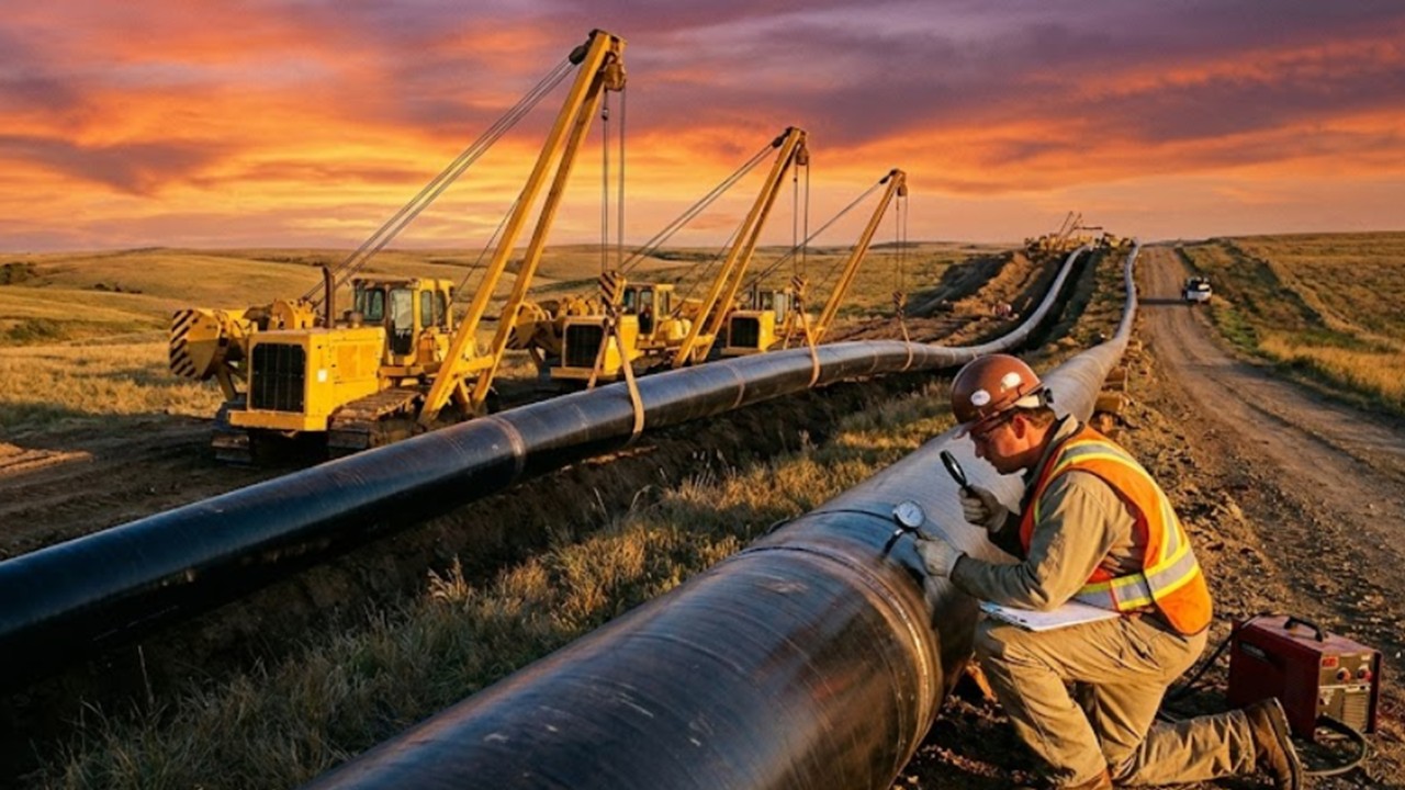
ASME B31 Pipeline Codes act as the fundamental constitution for the safe design, construction, and maintenance of pressure piping systems globally. Whether you are engineering a crude oil transmission line or a municipal natural gas distribution network, selecting the correct code section determines the mechanical integrity and legal compliance of your asset. In this guide, we break down the critical distinctions between liquid and gas standards to ensure your projects meet the rigorous demands of 2026 regulations.
What Are the ASME B31 Pipeline Codes?
The ASME B31 series prescribes minimum requirements for the design, materials, fabrication, testing, and inspection of piping systems. The two primary codes for transmission pipelines are:
- ➤ ASME B31.4: Pipeline Transportation Systems for Liquids and Slurries (Oil, Water, LPG).
- ➤ ASME B31.8: Gas Transmission and Distribution Piping Systems (Natural Gas, Hydrogen blends).
⚡ Engineering Knowledge Check: 2026 Edition
Loading Quiz…
Complete Course on
Piping Engineering
Check Now
Key Features
- 125+ Hours Content
- 500+ Recorded Lectures
- 20+ Years Exp.
- Lifetime Access
Coverage
- Codes & Standards
- Layouts & Design
- Material Eng.
- Stress Analysis
The Core Distinctions: ASME B31.4 vs B31.8 Difference
When engineers navigate ASME B31 Pipeline Codes, the most critical decision happens at the project’s inception: determining the transported medium. While both codes fall under the B31 umbrella, the ASME B31.4 vs B31.8 difference is not merely about fluid type—it represents a fundamental divergence in safety philosophy and risk management.
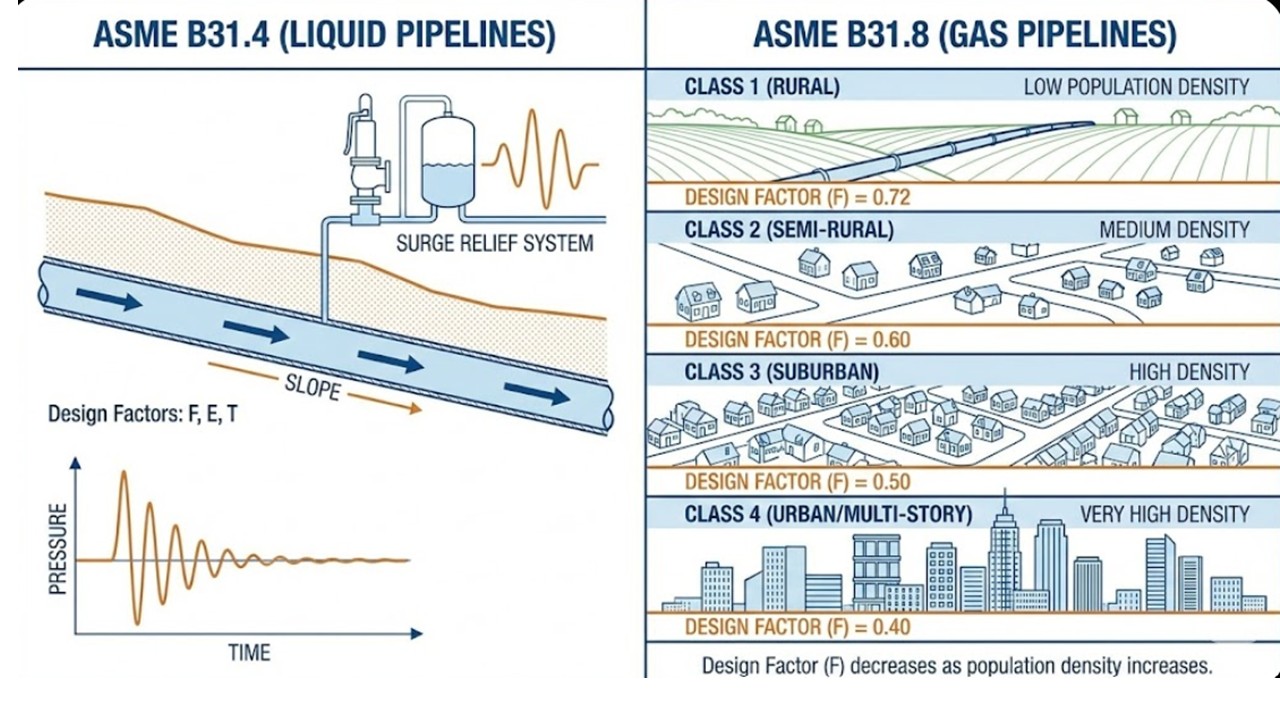
ASME B31.4 (Liquids) operates on the principle that liquids are incompressible; a rupture results in a rapid drop in pressure with localized energy release. Conversely, ASME B31.8 (Gas) governs compressible fluids where stored energy is massive. Consequently, the gas code introduces “Class Locations”—a demographic-based safety system that is absent in the liquid code.
Pipeline Wall Thickness Calculation & Physics
The heart of any ASME B31 Pipeline Codes compliance check is the determination of the pipe’s containment capability. This is governed by the hoop stress formula pipeline engineers use, commonly known as Barlow’s Formula, modified by specific safety factors defined in the code.
Governing Equation: Modified Barlow’s Formula
P = (2 × S × t × F × E × T) / D
- P = Design Pressure (psig)
- S = Yield Strength (SMYS) (psi)
- t = Nominal Wall Thickness (in)
- F = Design Factor (0.72 – 0.40)
- E = Longitudinal Joint Factor
- T = Temperature Derating Factor
*Note: The Pipeline wall thickness calculation rearranges this formula to solve for t.
In ASME B31.4, the Design Factor (F) is typically constant at 0.72 for main lines. However, B31.8 requires a variable factor depending on human activity near the pipeline, which leads us to the critical concept of Class Locations.
Understanding Class Location Factors B31.8
Unlike liquid lines, gas pipelines move through zones categorized by population density. ASME B31 Pipeline Codes (specifically B31.8) mandate that as the number of buildings increases, the safety margin must increase (i.e., the Design Factor must decrease). These are the Class location factors B31.8 specifies:
| Class Location | Description (1-Mile Unit) | Design Factor (F) | Max Usage |
|---|---|---|---|
| Class 1 | 10 or fewer buildings intended for human occupancy. | 0.72 | Remote Deserts, Farmland |
| Class 2 | More than 10 but fewer than 46 buildings. | 0.60 | Rural fringes, Industrial areas |
| Class 3 | 46 or more buildings OR within 100 yards of a playground/assembly area. | 0.50 | Suburban housing, Shopping centers |
| Class 4 | Buildings with 4+ stories prevalent (High Density). | 0.40 | City Centers (Manhattan, London) |
*Table 1: Evolution of Design Factors based on population density per ASME B31.8-2026.
Quick Reference: Liquid vs. Gas Parameters
To summarize the technical requirements for ASME B31 Pipeline Codes, the table below highlights the divergence in testing and materials.
| Parameter | ASME B31.4 (Liquid) | ASME B31.8 (Gas) |
|---|---|---|
| Fluid Type | Crude Oil, Liquid Products, LPG, Anhydrous Ammonia | Natural Gas, Hydrogen Blends |
| Design Factor (Max) | 0.72 (Generally constant) | 0.72 down to 0.40 (Variable) |
| Hydrotest Pressure | Typically 1.25 × MOP | 1.1 × to 1.5 × MOP (Class dependent) |
| Surge Analysis | Mandatory (Water hammer risk) | Not applicable (Compressible fluid) |
Field Engineering Report
Case Study: ASME B31 Pipeline Codes Failure Analysis
Asset Profile
- Asset: 24-inch Natural Gas Transmission
- Material: API 5L X60 Carbon Steel
- Original Install: 1995 (Class 1 Location)
- Standard: ASME B31.8 (Gas)
Failure Conditions
- Pressure: 950 PSIG (MOP)
- Environment: Urban Encroachment (Shift to Class 3)
- Defect: Stress Corrosion Cracking (SCC)
The Challenge: Urban Encroachment & SCC
A high-pressure gas transmission line originally constructed in a remote farmland area (Class 1) was subjected to rapid suburban expansion over three decades. By 2026, the area had developed into a high-density residential zone, technically shifting the requirement to Class 3.
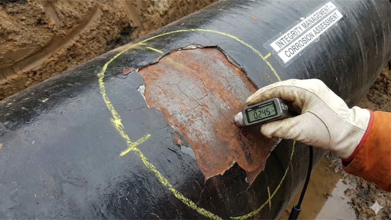
The operator’s pipeline integrity management systems (IMP) flagged a section of the pipe during a smart pig run. The ILI (In-Line Inspection) tool data suggested metal loss. Upon excavation, engineers discovered significant Stress Corrosion Cracking (SCC). The root cause analysis revealed that the pipeline was operating at a stress level acceptable for Class 1 (72% SMYS) but dangerously high for a Class 3 location (limit 50% SMYS), exacerbating the crack growth rate.
Engineering Solution: B31.8 Retrofit
To bring the section back into compliance with ASME B31 Pipeline Codes, the engineering team had to choose between lowering the operating pressure significantly or replacing the pipe segment.
- Step 1 (Calculation): Recalculated wall thickness using the Class 3 Design Factor (F = 0.50). The existing 0.250″ wall thickness was insufficient.
- Step 2 (Replacement): A 2-mile segment was cut and replaced with 0.500″ wall thickness pipe (API 5L X65) to maintain the original MOP while satisfying the stricter safety factor.
- Step 3 (Verification): The team executed rigorous pressure testing.
Validation & Result
Post-installation, the new segment underwent validation according to strict hydrostatic testing pressure requirements. Per ASME B31.8 for Class 3 locations, the test pressure was raised to 1.5 times the Maximum Operating Pressure (MOP) for 8 hours to ensure absolute containment integrity near the residential zone.
ROI & Safety: The proactive replacement prevented a potential catastrophic rupture. The project demonstrated how dynamic ASME B31 Pipeline Codes are; they are not static rules but evolving frameworks that must adapt to changing environments (Class Locations) to ensure public safety.
EPCLand YouTube Channel
2,500+ Videos • Daily Updates
Frequently Asked Questions: ASME B31 Compliance
What is the main difference between ASME B31.3 and B31.4/B31.8?
The distinction lies in the facility type. ASME B31.3 governs “Process Piping” (typically inside refinery or plant boundaries), dealing with complex chemistry and high temperatures. In contrast, ASME B31 Pipeline Codes (B31.4 and B31.8) govern “Transportation Piping” (cross-country lines), focusing on long-distance transmission, terrain compliance, and public safety corridors.
How does the hoop stress formula pipeline calculation change for gas lines?
While the base physics (Barlow’s Formula) remains consistent, the application changes via the Design Factor (F). For liquid lines (B31.4), F is usually constant (0.72). For gas lines (B31.8), the hoop stress formula pipeline calculation must input a variable F (0.72, 0.60, 0.50, or 0.40) based on the Class Location to increase wall thickness in populated areas.
When do Class location factors B31.8 require a pipeline upgrade?
A “Class Change” occurs when development (housing, businesses) increases near a pipeline segment, moving it from a lower class (e.g., Class 1) to a higher class (e.g., Class 3). This triggers a review of the Class location factors B31.8 mandates. The operator must either reduce the Maximum Operating Pressure (MOP) to meet the new safety factor or replace the pipe with thicker steel.
What are the standard hydrostatic testing pressure requirements?
Hydrostatic testing pressure requirements dictate that pipelines must be tested above their operating pressure to verify integrity. For B31.4 (Liquids), this is typically 1.25 times the MOP for 4 hours. For B31.8 (Gas), it ranges from 1.1 times to 1.5 times the MOP depending on the Class Location, often requiring longer hold times (8+ hours).

Related posts:
![High-grade industrial Wing Nut Types and Applications for mechanical assemblies.]()
Wing Nut Types and Applications: The 2026 Engineering Guide
![Industrial Monorail Crane Systems installed in a modern manufacturing plant 2026.]()
Monorail Crane Systems: Design, Types & 2026 Standards Guide
![Lead engineer performing a Factory Acceptance Test FAT on an industrial skid system 2026]()
Factory Acceptance Test FAT: The 2026 Engineering Guide to Zero-Defect Delivery
![Professional engineering workspace showing a Basis of Design document layout for a 2026 project.]()
Basis of Design: How to Write a BOD for Engineering Projects in 2026
![Industrial Flare Knockout Drum Sizing and installation in a refinery relief system.]()
Flare Knockout Drum Sizing: Design & API 521 Standards (2026 Guide)
![Advanced Reboiler Control Systems in a modern petrochemical refinery 2026.]()
Reboiler Control Systems: Engineering Guide to Precision Control 2026


