Understanding API 650: The Standard for Aboveground Storage Tanks
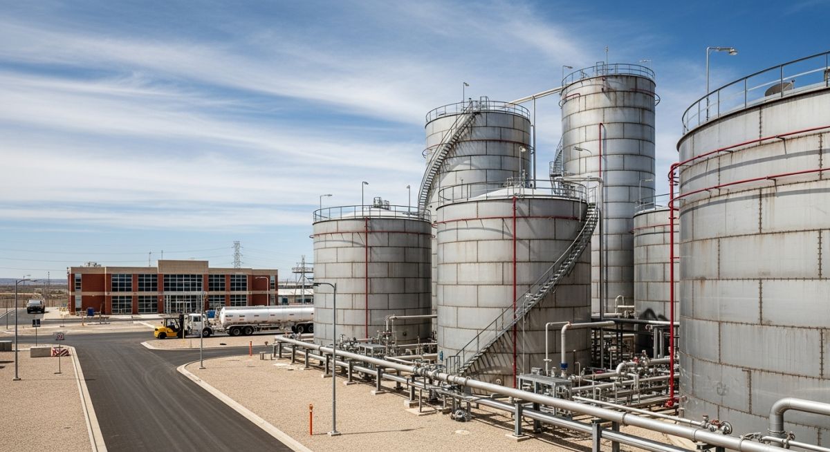
In my 20-plus years of managing terminal construction projects, I have seen how a minor oversight in tank shell calculations can lead to catastrophic field failures. When we talk about atmospheric storage, the industry bible is API Standard 650. This standard provides the mechanical engineering blueprint to ensure that these massive structures can safely withstand hydrostatic pressures, wind loads, and seismic forces without buckling or leaking.
Designing a tank is not just about welding steel plates together. It requires a deep understanding of material limits, environmental conditions, and joint efficiencies. Throughout my career, I have guided engineering teams through the complex calculations required by this code, ensuring compliance with safety and environmental regulations.
Key Engineering Takeaways
- Learn the exact mathematical formulas used to calculate shell plate thickness.
- Understand the critical differences between the One-Foot Method and the Variable-Design-Point Method.
- Identify the mandatory non-destructive testing protocols required before commissioning.
- Discover how to select the correct steel grades based on minimum design metal temperatures.
How Does API 650 Govern Tank Design?
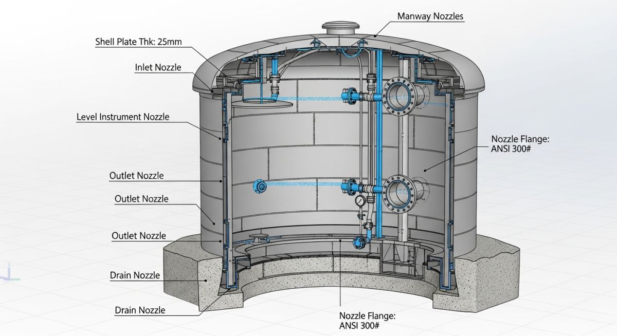
The primary structural component of any aboveground storage tank is its cylindrical shell. Under API 650 guidelines, the thickness of these shell plates must be calculated for both the design condition (filled with process fluid) and the hydrostatic test condition (filled with water).
The One-Foot Method (OFM)
The One-Foot Method calculates the thickness required at a point 0.3 meters (1 foot) above the bottom of each shell course. This method is valid for tanks with a nominal diameter of 61 meters (200 feet) or less.
Design Shell Thickness (td):
td = (4.9 * D * (H – 0.3) * G) / Sd + CA
Hydrostatic Test Shell Thickness (tt):
tt = (4.9 * D * (H – 0.3)) / St
Where:
- td = design shell thickness, in millimeters
- tt = hydrostatic test shell thickness, in millimeters
- D = nominal tank diameter, in meters
- H = design liquid height, in meters
- G = design specific gravity of the stored liquid
- Sd = allowable stress for the design condition, in Megapascals
- St = allowable stress for the hydrostatic test condition, in Megapascals
- CA = corrosion allowance, in millimeters
The governing thickness is always the larger value of td or tt. In my experience, engineers often forget to add the corrosion allowance to the design thickness while keeping the hydrostatic test thickness free of corrosion allowance. This is because the hydrotest is a short-term event conducted before the tank enters corrosive service.
Field Warning: Material Substitution Risks
Never substitute shell plate materials without verifying their impact on the design temperature limit. Using non-impact-tested carbon steel below the Minimum Design Metal Temperature (MDMT) curve can lead to sudden brittle fracture, especially in cold-climate installations.
The Variable-Design-Point Method (VDPM)
When tank diameters exceed 61 meters, the One-Foot Method becomes overly conservative, leading to excessively thick and expensive shell plates. In these scenarios, API 650 permits the use of the Variable-Design-Point Method. This approach calculates the exact point of maximum stress on each shell course, which is typically lower than the 0.3-meter mark used in the OFM. This optimization reduces material weight and welding costs significantly.
Selecting the correct steel grade is critical for structural integrity. The table below outlines common ASTM materials approved under API 650, along with their allowable design and testing stresses.
| ASTM Material Grade | Minimum Yield Strength (MPa) | Minimum Tensile Strength (MPa) | Allowable Design Stress Sd (MPa) | Allowable Test Stress St (MPa) |
|---|---|---|---|---|
| ASTM A36 | 250 | 400 | 160 | 171 |
| ASTM A516 Gr. 70 | 260 | 485 | 194 | 208 |
| ASTM A573 Gr. 70 | 260 | 485 | 194 | 208 |
| ASTM A283 Gr. C | 205 | 380 | 137 | 154 |
This matrix maps the core technical entities, structural acronyms, and physical parameters defined across various sections of the standard.
| Entity / Acronym | Technical Definition | Physical Parameter Limits | Standard Reference |
|---|---|---|---|
| MDMT | Minimum Design Metal Temperature based on local climate data. | Down to -40 degrees Celsius | API 650 Sec. 4.2.2 |
| Joint Efficiency (E) | Value representing the integrity of welded joints based on radiography. | 0.70 to 1.00 | API 650 Table 5.2 |
| Plummet (Out-of-Plumb) | Maximum allowable vertical deviation of the tank shell. | H / 200 maximum | API 650 Sec. 7.5.2 |
| Peaking | Localized distortion at vertical weld joints measured with a sweep board. | 13 millimeters maximum | API 650 Sec. 7.5.4 |
What Are the API 650 Inspection Requirements?
During the construction phase, quality control is your only defense against future leaks. I have managed several tank builds where rigorous inspection caught weld defects that could have resulted in environmental disasters. The following checklist outlines the mandatory inspection steps required by API 650 Section 7 and 8.
Field Inspection & Verification Checklist
-
Foundation Leveling Survey: Verify that the concrete ringwall or asphalt foundation is level within 3 millimeters in any 10 meters of circumference, and within 6 millimeters overall.
-
Bottom Plate Vacuum Box Testing: Apply a soap solution to all lap-welded bottom joints and test using a vacuum box at a minimum pressure of 21 kilopascals (3 pounds per square inch) to check for bubble formation.
-
Radiographic Examination (RT): Perform radiography on vertical and horizontal butt welds in accordance with API 650 Section 8.1. Ensure film density and sensitivity meet ASME Section V requirements.
-
Plummet and Roundness Check: Measure the verticality (plumbness) of the shell. The maximum out-of-plumbness of the top of the shell relative to the bottom must not exceed 1/200 of the total tank height.
-
Hydrostatic Testing: Fill the tank with water to the maximum design liquid level and hold for at least 24 hours. Monitor for settlement, shell deformation, and joint leakage.
Field Case Study: Real-World Application
The Problem: Brittle Fracture Risk in Cold-Climate Terminal
During a terminal expansion project in northern Alberta, Canada, a contractor proposed using standard ASTM A36 steel plates for a 50,000-barrel crude oil storage tank. The minimum design metal temperature (MDMT) at the site was determined to be -29 degrees Celsius.
Upon reviewing the design package, I realized that standard ASTM A36 without impact testing falls into Group I of the API 650 material curves. At a thickness of 22 millimeters for the lower shell course, this material was highly susceptible to brittle fracture at the design temperature, posing a severe risk of sudden, catastrophic tank failure.
The Outcome: Material Upgrade and Safe Commissioning
I immediately halted the procurement process and instructed the engineering team to perform a complete material re-evaluation. We upgraded the lower shell courses to ASTM A516 Grade 70 (normalized), which belongs to Group V of the API 650 material curves. This material provides excellent low-temperature toughness and impact resistance down to -40 degrees Celsius.
The tank was fabricated, welded, and subjected to 100% radiography on all vertical joints. The subsequent hydrostatic test was completed successfully during the spring thaw. By enforcing strict compliance with API 650 material group limits, we prevented a potential brittle failure that could have cost millions in environmental cleanup and structural damage.
My recommendation for any engineer working in cold climates is to always establish the site-specific MDMT before finalizing the material data sheets. Never rely on standard carbon steels without verifying their impact testing requirements under API 650 Figure 4.1.
Frequently Asked Engineering Questions
What is the maximum design pressure allowed under API 650?
What is the difference between API 650 and API 653?
When is radiographic testing (RT) mandatory for shell welds?
Can we use lap-welded joints for the tank shell?
How does the specific gravity of the liquid affect the design?
What is the purpose of an annular bottom plate?
===
Complete Course on
Piping Engineering
Check Now
Key Features
- 125+ Hours Content
- 500+ Recorded Lectures
- 20+ Years Exp.
- Lifetime Access
Coverage
- Codes & Standards
- Layouts & Design
- Material Eng.
- Stress Analysis

📚 Recommended Resources: API 650 standard
Read these Guides
- 📄 Tank Pad Foundation: The 2026 Engineering Guide to API 650 Standards
- 📄 API Standards: The Complete 2026 Engineering Guide (API 610, 650 & 570
- 📄 Piping Materials vs Pipeline Materials: Key Differences and Engineering Standards
- 📄 What is Metallic Piping: Types, Advantages, Applications, and ASTM Standards